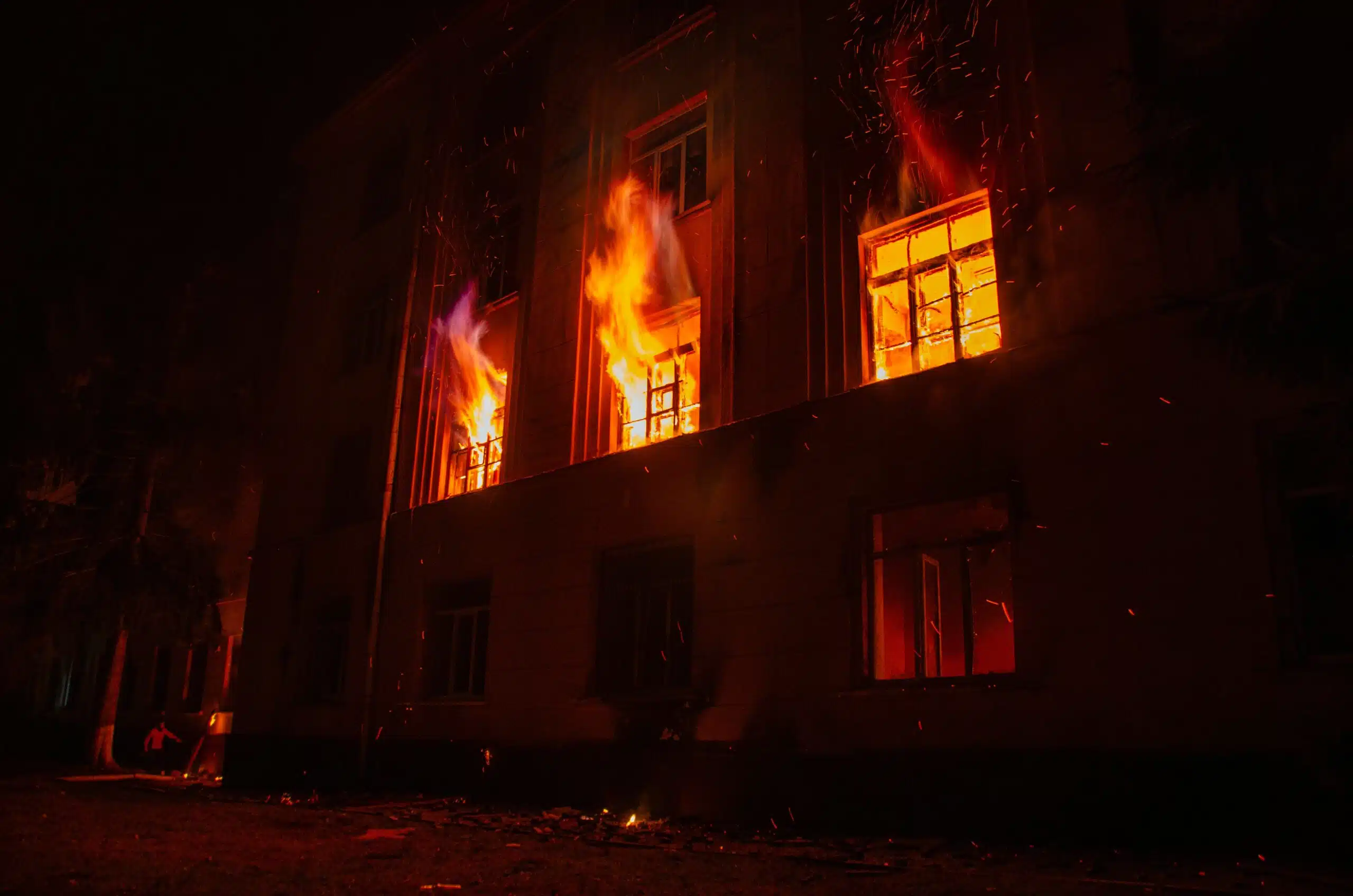
Provisions for natural smoke control
Natural-draught smoke control is carried out using natural smoke exhausts and air inlets, positioned so as to ensure a good sweeping of the area concerned. These elements communicate directly with the outside or through ducts.
Smoke exhausts
- Roof vents
- Façade openings
- Vents
Air inlets
- Façade openings
- The doors of rooms opening onto the outside or onto largely ventilated volumes
- Non-enclosed staircases
- Vents
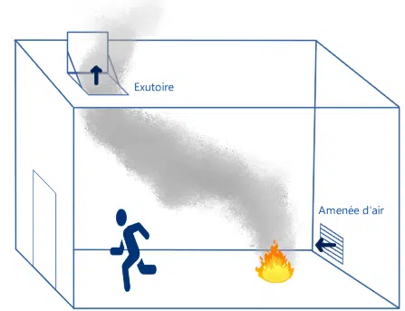
No opening may have a dimension smaller than 20 centimetres. Where the volume to be cleared of smoke is semi-buried and the air supply cannot be natural, mechanical air inlets may exceptionally be used: they can then only be combined with roof vents, and the air velocity at the vent outlet is limited to 5 m/s.
Provisions for mechanical smoke control
Mechanical-draught smoke control is achieved using mechanical extractors together with air inlets, either natural or mechanical, distributed so as to ensure a sweeping flow. In addition to sweeping the smoke, it is possible to add a pressurisation of the spaces to be protected.
Smoke extraction and mechanical air supply are provided by vents connected to an extraction fan. As indicated earlier, the air velocity at the air inlets must not exceed 5 m/s; they must also have a flow rate of about 0.6 times the extraction flow rate.
The smoke-control fans must comply with the NF EN 12101-3 standard and bear the CE marking. They must provide a resistance to hot smoke of 400 °C for 90 minutes. Their sizing must take into account the losses due to leakage and pressure drops.
Duct characteristics
For natural smoke control, two rules must be respected by the ducts in order to solve the problems related to the pressure drops generated:
Duct rules (natural)
- The ratio between the largest dimension and the smallest dimension must be ≤ 2.
- The duct cross-section must be equal to or greater than the free area of the vents it serves.
Vertical exhaust ducts may not have more than two deviations, with a maximum angle of 20 degrees. The horizontal floor branches (horizontal storey connections of the exhaust ducts) must have a maximum length of 2 metres, unless an adequate flow rate is demonstrated. To justify this flow rate, a calculation must be carried out assuming that the smoke has a temperature of 70 °C, that the outdoor temperature is +15 °C and that there is no wind.
Enclosed circulation
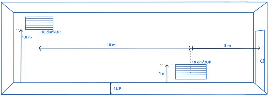
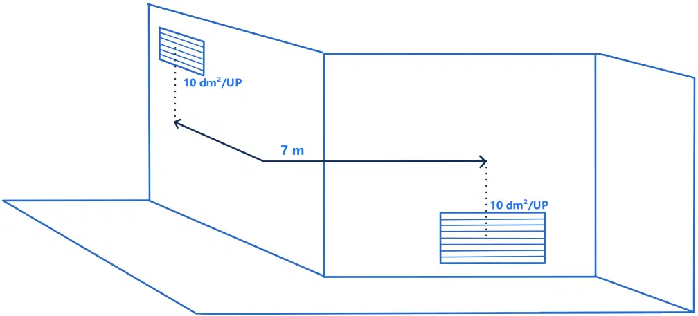
The air-inlet and extraction vents are positioned in an alternating manner. In the case of a straight circulation, the maximum distance between the air inlet and the extraction is 10 metres; if the circulation is not straight, the maximum distance is 7 metres. To place the first vent, you must measure 5 metres from the axis of the first door accessible to the public.
Positions & areas
- Air inlets: upper edge at most 1 metre above the floor.
- Smoke exhausts: lower edge of the ducts at least 1.8 metres above the floor, entirely positioned in the upper third of the circulation zone.
- Free area of 10 dm² per unit of passage (UP); if a single extraction vent serves two air inlets, the extraction must have a free area of 20 dm² per UP.
Case 1 (generic): the room
Sizing rules
Rooms ≤ 1,000 m²
- Effective exhaust area: minimum 1/200 of the room area, or calculated via the table for rooms > 1,000 m² with the α ratio.
- Free area of the air inlets: equal to the geometric area of the smoke exhausts.
Rooms > 1,000 m²
- Effective NSHEV area: determined by the type of operation (building class) and the α ratio.
- Minimum smoke-zone value of 1,000 m² (even if smaller).
- Effective area = α ratio × smoke-zone area.
- Air inlets: equal to the geometric area of the exhausts.
Case 2: staircase & case 3: smoke zone
Case 2 — the staircase
The natural sweeping of a stairwell is achieved by an exhaust device located:
Sizing rules (staircase)
- On the roof with a geometric area (Av) of 1 m², or on the façade with a free area (SLC) of 1 m² at the top of the stairwell.
- AND, in both cases, an air inlet at the bottom of the stairwell of 1 m² free area (SLC).
- Control device at the lower level of the staircase.
- Reset (closing) possible from the bottom of the staircase or the top landing.
The natural smoke control of staircases is a system independent of the establishment's fire-safety system. Staircase smoke-control installations are qualified in the NF S61-932 standard of July 2015. If natural smoke control is not possible, the staircase must be pressurised by a mechanical air supply, which must be combined with the smoke control of the directly connected volume.
Case 3 — the smoke zone
The determination of smoke zones is defined in Technical Instruction 246:
Sizing rules (smoke zone)
- Smoke zone mandatory for rooms larger than 2,000 m² or more than 60 metres long.
- Maximum area of a smoke zone: 1,600 m² or 60 metres in length.
- Thickness of the smoke layer: if H ≤ 8 m, between 25 % and 50 % of the reference height; if H > 8 m, between 2 metres and 50 % of the reference height.
- Smoke-free height (HL) never less than 1.8 metres.
ERP smoke control, circulations, staircases, smoke zones: our engineers build and validate your file through simulation.