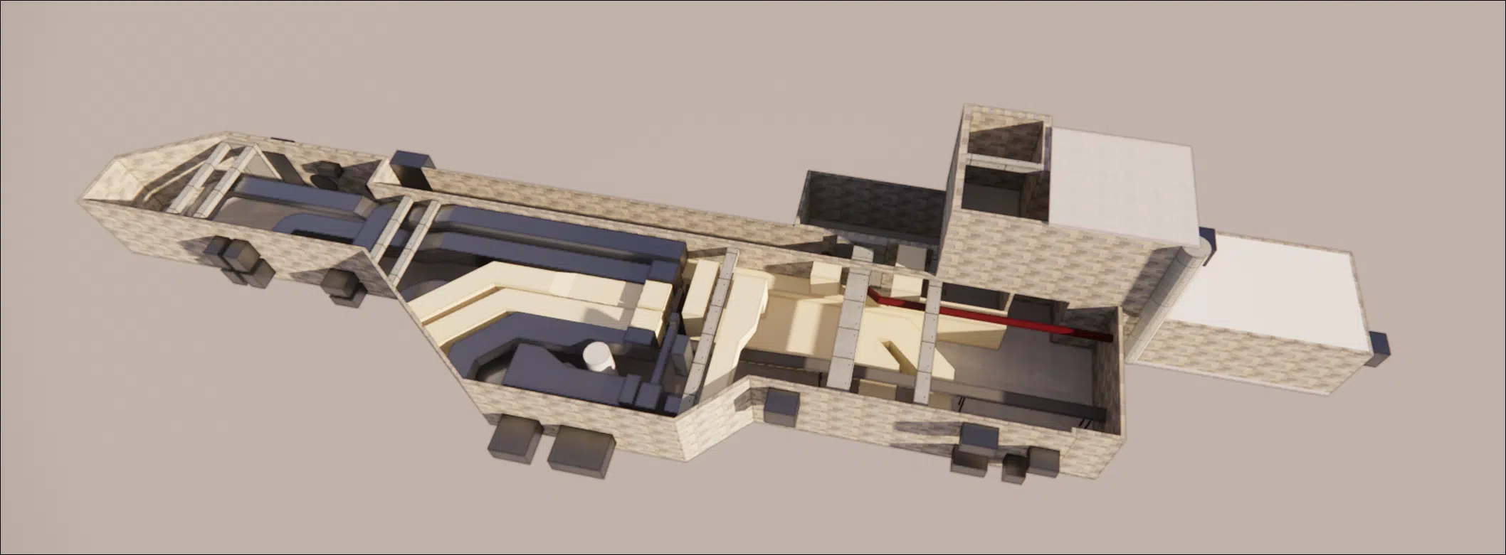
What is CFD simulation?
In this article we look at understanding CFD simulation in a general way, detailing the various steps common to the different types of simulation (HVAC engineering, hydrology, heat transfer, pollution dispersion, fire safety…).
Definition of CFD
CFD (Computational Fluid Dynamics) is the branch of fluid mechanics that numerically solves the Navier-Stokes equations to simulate and analyse fluid flow as well as the associated heat and mass transfer and chemical reactions. The study domain is divided into a mesh of finite volumes over which the conservation equations — mass, momentum, energy — are discretised and then solved iteratively on high-performance computers (HPC, GPU acceleration). The simulation reconstructs, at every point and every instant, physical quantities — velocity, pressure, temperature, turbulence — that are difficult, costly or impossible to measure experimentally, which today makes CFD a central tool for design, optimisation and validation.
Pourquoi utiliser la simulation CFD ?
CFD, short for “Computational Fluid Dynamics”, is an engineering tool that belongs to what is known as computer-aided engineering (CAE). More precisely, CFD refers to the simulation of fluid flow, taking into account the physical and chemical phenomena involved (such as turbulence, heat transfer or chemical reactions).
CFD simulation: an alternative to wind tunnel testing
Wind tunnel testing
Wind tunnel testing aims to reproduce the interaction between turbulent wind and structures. For structurally stiff works, it is possible to assess the aerodynamic loads on rigid models.
Wind tunnel testing has been widely used for industrial and civil-engineering applications over the past five decades.
Wind tunnel tests require a costly facility and sophisticated instruments to measure a range of field variables (wind speed, pressure loads, turbulence intensity, etc.). Their main limitation is that such measurements are only obtained at a few specific points of the test section, which considerably restricts the overall understanding of the evolving or transient processes of complex unsteady phenomena (such as vortex shedding, turbulent wakes and thermal stratification).
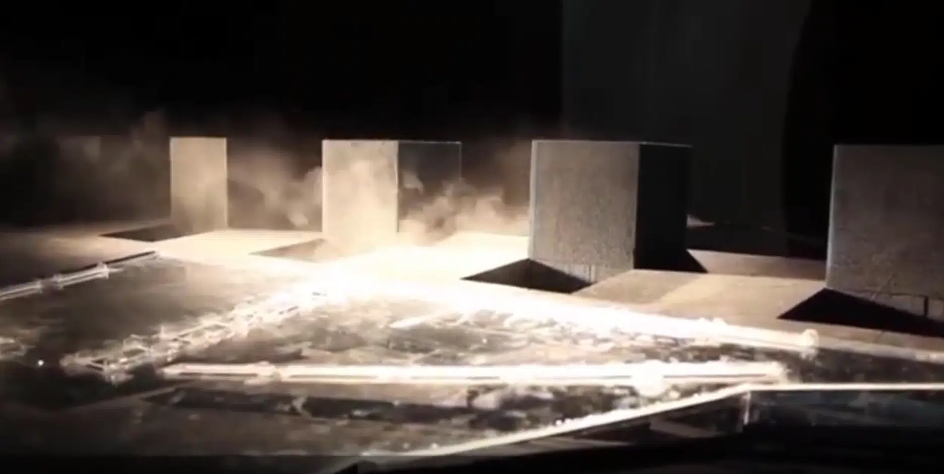
Studying natural ventilation in a wind tunnel
CFD simulation: a toolbox-style evolution
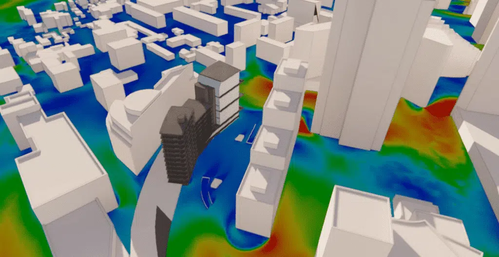
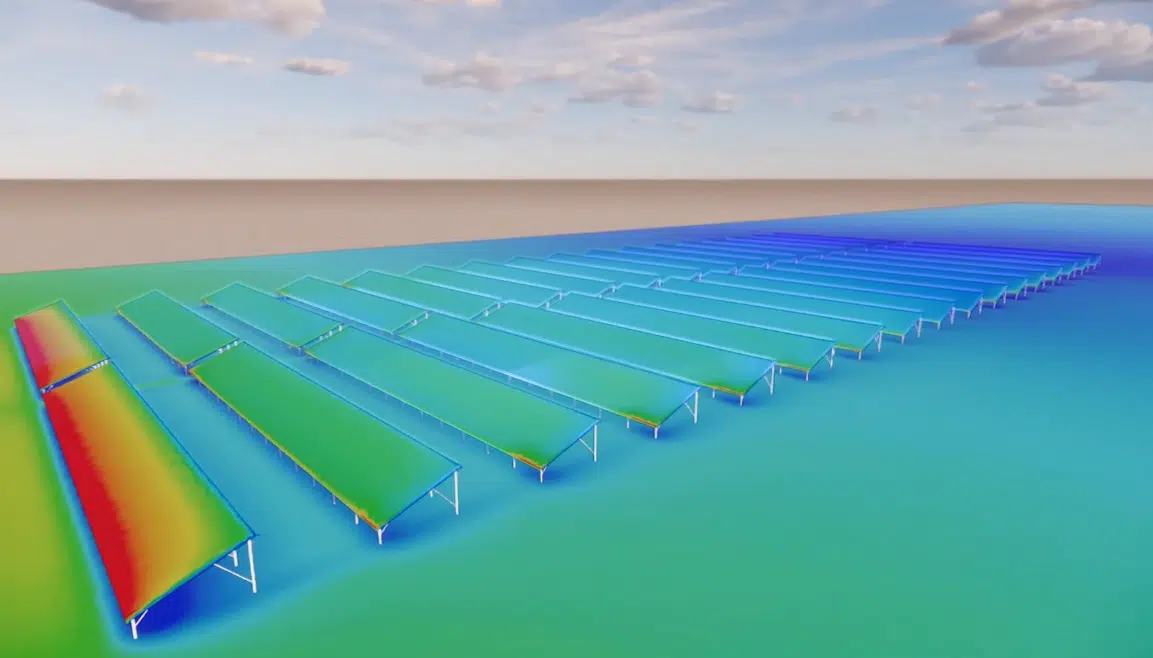
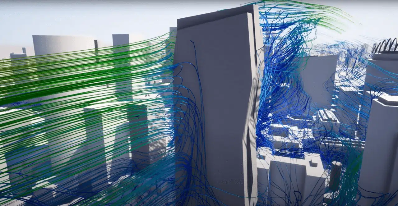
CFD offers many advantages for ventilation compared with wind tunnel testing. As well as generating full-scale simulations (rather than the reduced-scale models of many physical simulations), it also provides complementary data and makes it possible to compare, for a given wind, the wind speeds simultaneously between two points. It is possible to carry out hydrology, airflow or thermal studies at different scales: from microelectronics to building and city studies. The results can be visualised more clearly and explained to a wider audience.
CFD simulation: a very wide range of applications
General toolbox
- Simulate fluid flow around or inside a body
- Aerodynamics
- Study wind comfort (CFD comfort study)
- Wind-load study
Thermal toolbox
- Study convective exchanges
- Study conductive exchanges
- Study radiative exchanges
Multiphysics toolbox
- Visualise pollutant dispersion
- Study smoke control
- Study the movement of dust, sand…
- Study the movement of objects, fans, pumps…
Hydrology study
- Fluid flow
- Flooding risk
- Rain or snow risk
These methods solve a very wide range of problems, which we present below.
Que peut apporter l'utilisation de la simulation CFD ?
With CFD simulation, the design of a process or a product can be improved without building prototypes (costly in time and money); poor decisions can be avoided; a better understanding of the process or product is gained, making it possible to move faster through the design process (choosing the best solutions), as well as to solve problems that arise in facilities or processes already in operation.
As soon as the framework of a physical problem can be set out, it can be studied in CFD numerical simulation.
How is a CFD simulation project organised?
How long should you allow for a CFD project?
In general, a fluid-simulation project involves a preliminary study of the process or phenomenon to analyse, the creation of a detailed geometric model, the choice (and implementation if needed) of the appropriate mathematical models, the application of operating data as boundary conditions, the numerical computation (which can range from a few minutes to a few days, depending on the complexity of the calculation) and the analysis of the results.
So, despite the applications developed in recent years to make it easier to use, running a CFD project properly requires experience and a significant investment of resources.
Defining the study problem
Before starting a design study, we need to ask you a few important questions. These questions are crucial to determine the geometry we will start the analyses with, the parts of your design to focus on and the parameters to observe once the analysis is complete.
Understanding your problem
- What are the operating conditions of this design?
- What materials are used in this design?
What you want to know about performance
- What are the objectives of this design?
- Are there success or failure criteria?
What you can change
- Can you change the operating conditions?
- Can you change materials?
- Which parts of the design can be changed?
Once these answers are obtained, improving our understanding of the stakes, we detail here the CFD modelling process common to all types of project.
Preparing the 3D model
How is the 3D CFD study model built?
An effective simulation starts with good modelling techniques, both in terms of model integrity and the proper creation of the various fluid-flow regions and mesh optimisation. The first step is to design a model for the fluid-flow analysis. This means modelling the geometry where the flow occurs and optimising the model for simulation.
Optimising the model for simulation
The problem
- Production geometry can contain spaces, gaps and details made up of many small features, detrimental to CFD simulation.
- These features, often necessary for manufacturing, add unnecessary complexity to the simulation: we keep only the elements that matter for the problem.
The methodology
- To save time and resources, we reduce the parts of the model that are too small to affect the results.
- For large assemblies, we keep only the critical parts of the design, which speeds up the solving.
- In some cases, we recreate a simplified version of your design to focus on the key study zones.
Repairing the 3D geometry
- Remove the spaces that prevent voids from being filled (gaps between parts, drill holes, joinery…).
- Reduce very large assemblies to include only the vital components.
- Remove the gaps between non-adjoining elements.
Preparing the 3D CFD model for mesh optimisation
To study fluid movement in a design, a model of the flow region must exist. Most 3D models do not include it by default: it then has to be created using software that completes the original 3D model. It also involves preparing the model for mesh optimisation in high-stakes zones. We therefore add 3D parts — invisible in renderings and in CFD studies — whose purpose is to allow the mesh to be precisely refined in the flow zones to be captured.
What is the mesh? (and why does it matter?)
Generating the (3D) mesh is an important phase of a CFD analysis, given its influence on the computed solution. A very high-quality mesh is essential to obtain a precise, robust and meaningful computation result.
Finite-element computations
Before running a CFD simulation, the geometry is divided into small pieces called elements. The corner of each element is a node. The computation is performed at the nodes. These elements and nodes make up the mesh.
In three-dimensional models, most elements are tetrahedra: a four-sided element with triangular faces. In two-dimensional models, most elements are triangles.
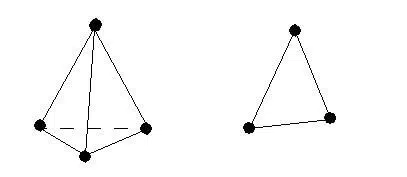
Mesh structure
We distinguish structured from unstructured meshes, orthogonal or free. In a 3D structured mesh, the computation is faster as it does not require assembling a connectivity matrix. In an unstructured mesh, this is not the case. Its advantage is that it can mesh arbitrary geometries; however, creating and storing the matrix can greatly slow the computation. This type of mesh is used for complex geometries with curves or a large number of elements.
Solid volumes need few elements, unlike fluid volumes, which require precise refinement because they cannot stray from a parallelepiped geometry; indeed, for highly distorted element angles, there is a risk that the computation cannot converge.
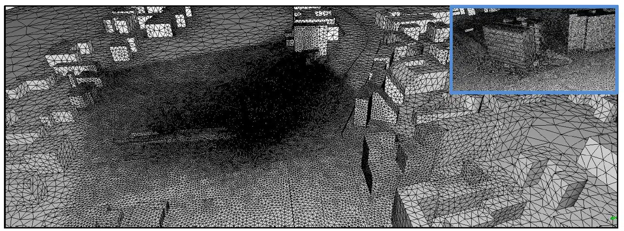
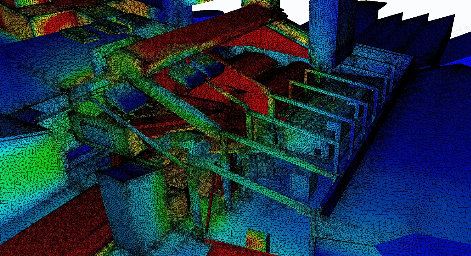
Mesh density
Regarding mesh density, the aim is to strike a compromise between the cost of computation time and the precision sought. There is no point refining the mesh — and therefore increasing the number of iterations — if the precision is sufficient with a limited number of elements.
Mesh adaptation principle
Mesh quality has a serious impact on convergence, on the accuracy of the solution and above all on the computation time. Good mesh quality relies on minimising the elements showing “distortions” and on good “resolution” in regions with a strong gradient (gap, boundary layers, recirculation…).
The mesh is adapted to be as fine as possible in the critical study zones. This captures the macroscopic phenomena (the building's volume) channelling stream tubes through the Venturi effect, while correctly capturing the smaller-scale airflow phenomena (air diffusion).
How are CFD boundary conditions defined?
Initial conditions
The initial conditions represent the flow characteristics in terms of velocity and free-surface position at the start of the simulation. If the computation begins with random values, the simulation may quickly diverge. To avoid straying too far from realistic results and to optimise computation time, the initial conditions are studied and chosen ahead of the CFD study.
Boundary conditions
The study of boundary conditions is decisive in a model; they can be summed up as the simulation's assumptions. This is the most decisive step for the success of the study: setting the project-specific boundary conditions must be studied in detail from the very start of the assignment.
Solving method
Selecting the turbulence model
The notion of a turbulence model is specific to fluid mechanics. It makes it possible to catalogue the different structures that coexist in a flow and to give them a certain weight within the flow.
Comparative studies of turbulence models by Combes [2000] identified the two-transport-equation k-ε model as the best suited to general-purpose flows. It is one of the most widely used, most efficient, simplest and most extensively validated models. k represents the turbulent kinetic energy and ε the dissipation rate of that turbulent kinetic energy. Logically, we will use it for most thermal-airflow and hydrology fluid simulations, but we can select other turbulence models for specific simulations.
Computation method
The numerical solution is carried out through the linearisation and discretisation of the full set of conservation equations, which requires subdividing the computational domain into a number of non-contiguous finite volumes (the mesh). Solving the study consists of solving the non-linear Navier-Stokes system of equations on compute servers dedicated to CFD.

Visualising the results
Graphical summaries
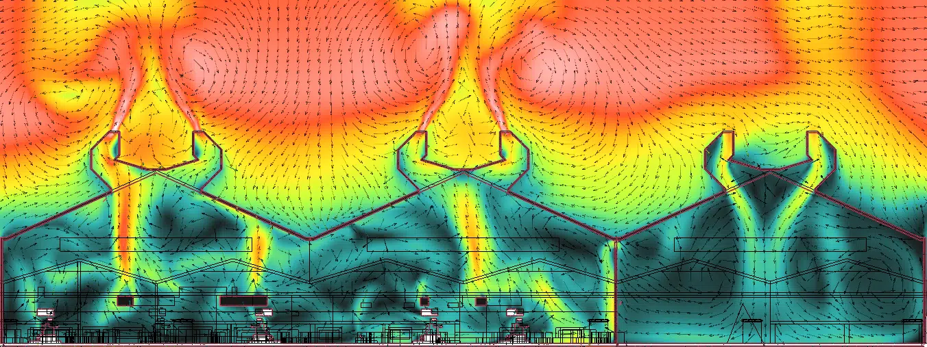
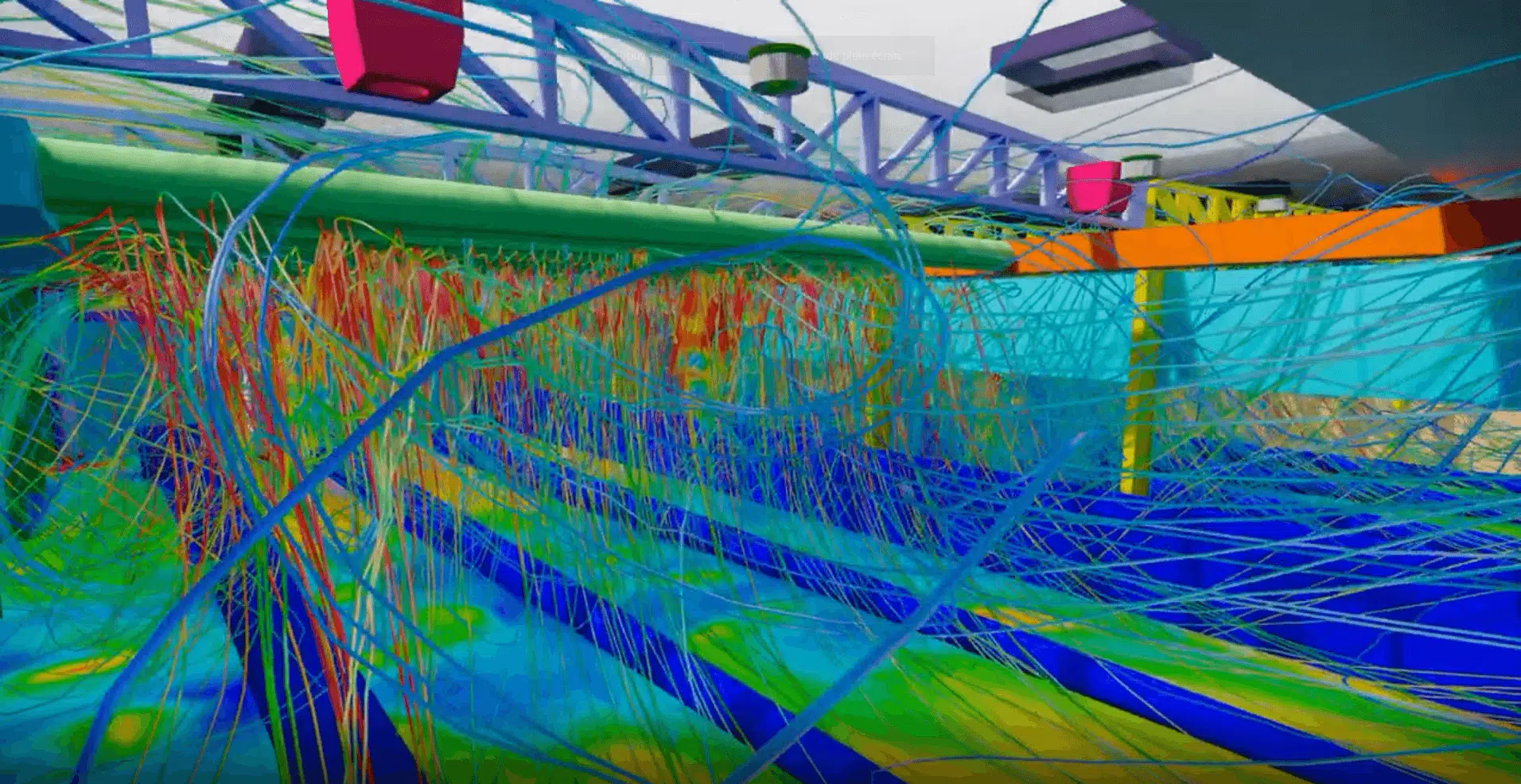
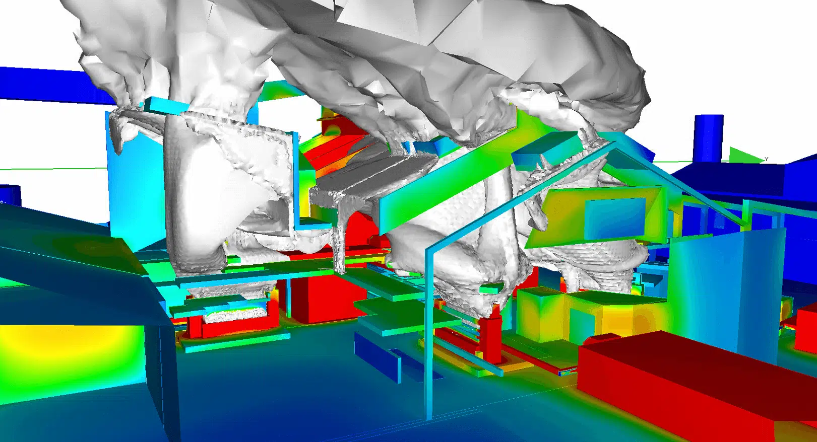
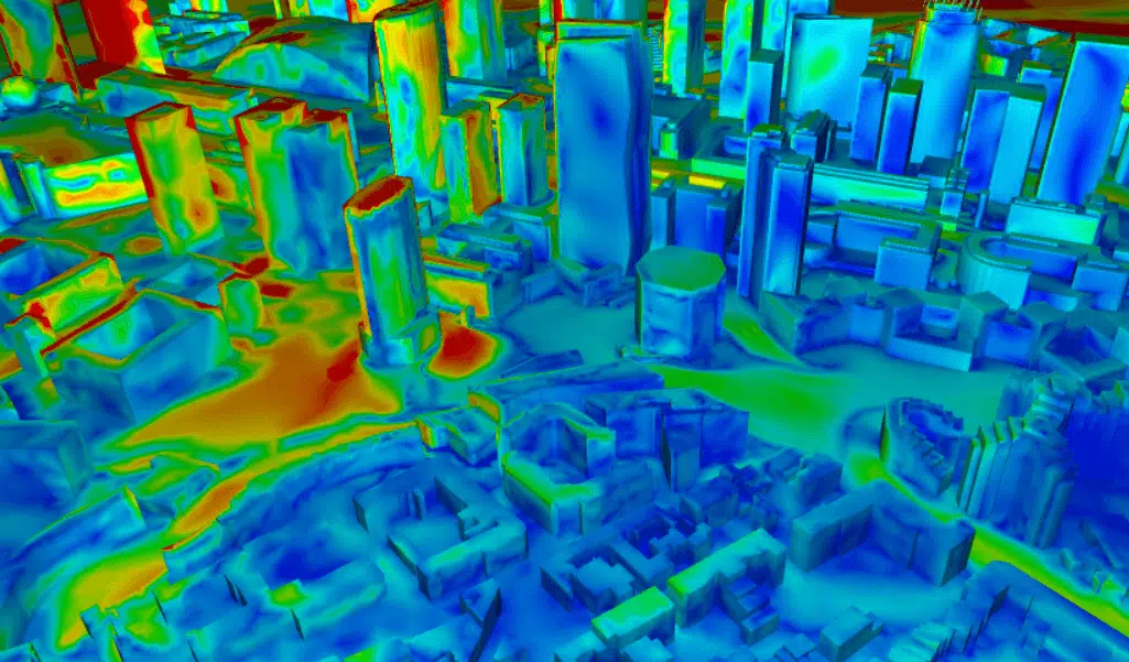
Fluid flow within a volume is generally complex and features many low-speed recirculations, which makes 2D visualisation difficult. We report the most significant phenomena through situation plans / slices accompanied by very thorough explanations.
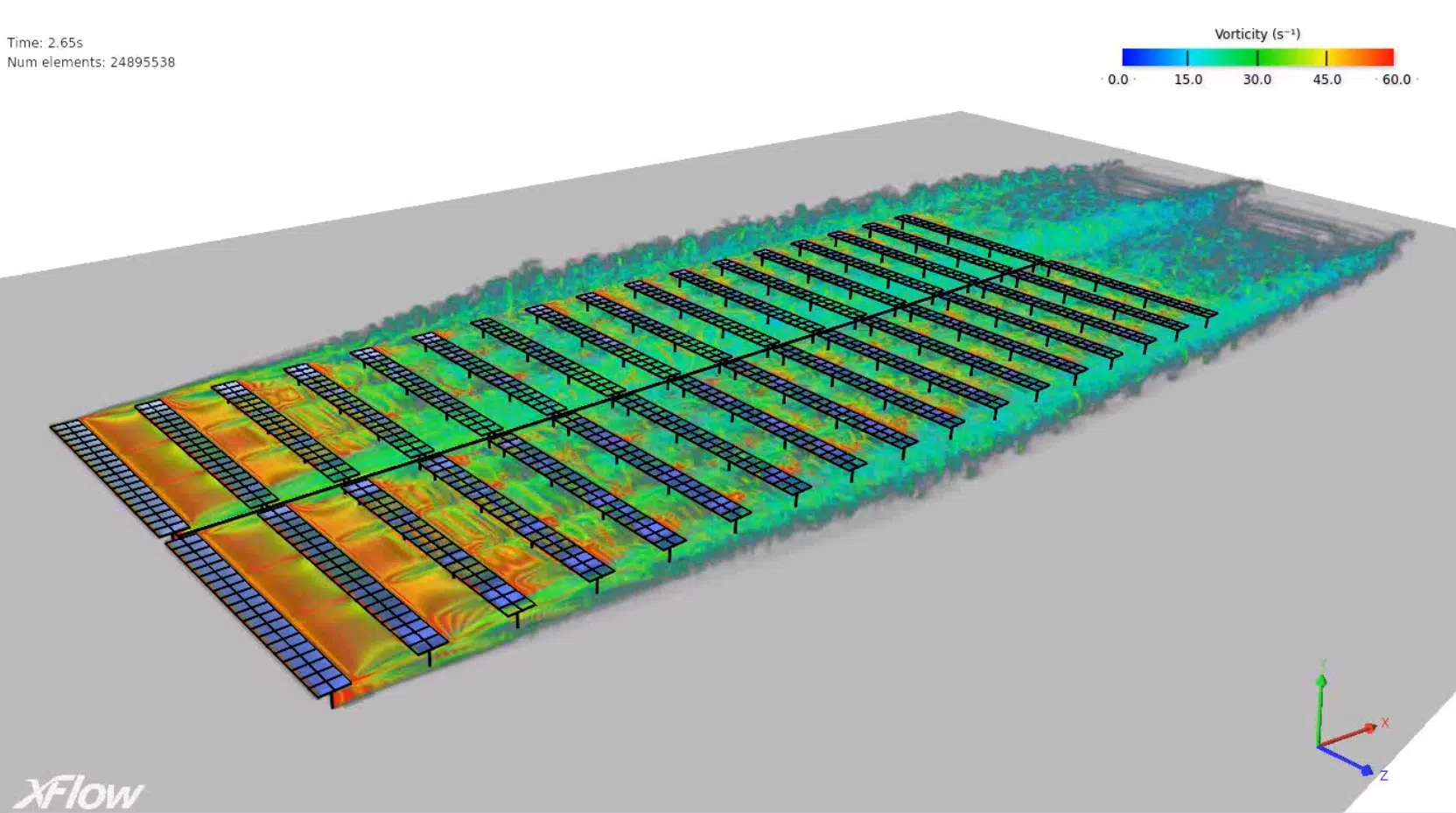
We have a wide range of representations (stream tube, vector field, isosurface…) that best convey the airflow phenomena identified in the technical report.
Interpreting the results requires mastery of the CFD analysis software but above all physics skills and knowledge of the product analysed in order to explain the various phenomena precisely.
Summary videos
From our experience, for the most striking elements, videos are produced showing the different views of the CFD model dynamically. The technical report can refer to these videos to make it easier to read — some phenomena being hard to grasp on a plan.
Pros and cons of CFD simulation
Advantages of CFD simulation
- Models can be simulated in full and allow the simultaneous analysis of the impact of many phenomena.
- Simulations provide measurement data for any point (of the grid).
- Many parameters, not accessible in experiments, can be recorded; designs can be made safe.
- Early in the design process, a large number of prototypes can be simulated to quickly gather information for system optimisation.
- Simulations contribute to a better understanding of the problem in order to develop relevant technical solutions.
- Integrating CFD simulation into your design protocols means bringing in a team of experts who will offer a different perspective when seeking solutions.
Drawbacks of CFD simulation
- Errors can occur due to models whose boundary conditions are too simple or wrong.
- Uncertainties are possible, due to insufficient computation values per cell and the resulting interpolation errors.
- Computation time for large models can be long.
These issues are very significantly reduced thanks to the experience EOLIOS engineers have gained on many projects. It is important to carry out this kind of study with a qualified team.
How much does a CFD simulation cost?
Let's be honest: CFD is not the cheapest engineering tool (compared with a standard CAD application or spreadsheet) given its complexity and requirements (experience, licences, computing resources).
On the other hand, the results this kind of study offers and their contribution to a design or problem-solving process cannot be compared with those obtained using simpler tools.
The reduction in design time, prototyping savings and improvement of the process or product generally offset the cost of CFD simulation. We offer assignment protocols suited to any budget.
If after reading this you think so, don't hesitate to contact us: we'll propose a clear, detailed study protocol.