
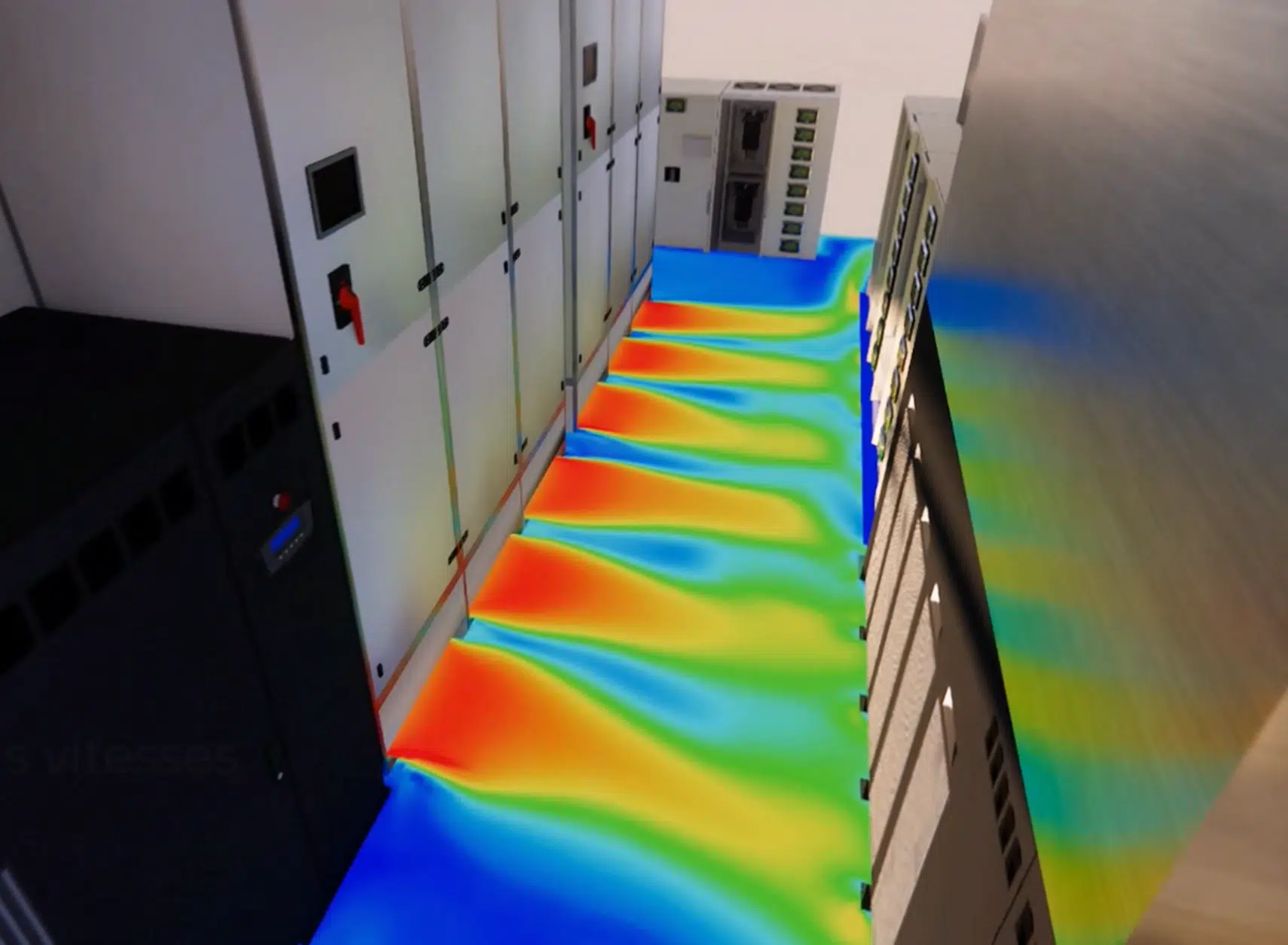
Thermal CFD study of the technical rooms of a data center in Meudon (UPS room, STS room and transformer room) for optimal performance and unrivalled reliability.
Faced with growing demand, the thermal management of the technical rooms is a major challenge. EOLIOS uses CFD to propose bespoke solutions guaranteeing performance, energy efficiency and reliability. The rooms studied, a UPS room, an STS room and a transformer room, are located in Meudon.
The essentials. Thermal CFD study of three technical rooms of a data center in Meudon (UPS, STS, transformers). The simulation reveals short-circuiting phenomena that recycle the hot air towards the intakes and create hot spots. The bespoke designs (full enclosure, ducting of the heat releases, raising of the CRAH intakes) eliminate the short-circuiting and lower the temperatures by 5 °C; a redundancy study confirms the behaviour with one CRAH shut down.
In the world of data centers, thermal management holds a central place. Usually, hot and cold aisles are arranged in the halls to optimise the cooling of the servers and equipment. However, when it comes to the technical rooms, the situation is quite different: each installation is unique, with its own constraints and configurations, which makes standardised cooling solutions often unsuitable.
In this context, expertise in CFD (Computational Fluid Dynamics) plays a key role. In the absence of established measurements and off-the-shelf solutions, it is essential to turn to advanced modelling tools to understand and optimise air circulation, heat dissipation and temperature distribution. Using CFD, an in-depth analysis of the infrastructures is carried out in order to identify the hot zones, optimise the airflows and design cooling solutions suited to these technical rooms.
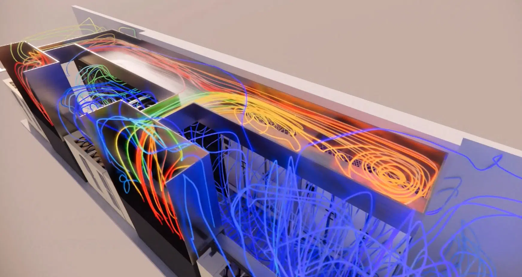
To build the 3D model of a technical room for the CFD study, the approach relies both on the room plans and on site visits. First, the detailed architectural plans of the room made it possible to recover the dimensions and the layout of the equipment. Then, during the site visit, more thorough observations and precise measurements were carried out, and specific details such as the cooling systems, the ventilation grilles and the obstacles were recorded.
Using 3D modelling software, geometric models of the rooms were created, incorporating the equipment and the obstacles of the room while respecting their real position. Finally, by assigning the appropriate physical properties to each element of the model (thermal conductivity of the materials, heat releases of the machines, performance of the air-conditioning systems), the CFD studies could be carried out.
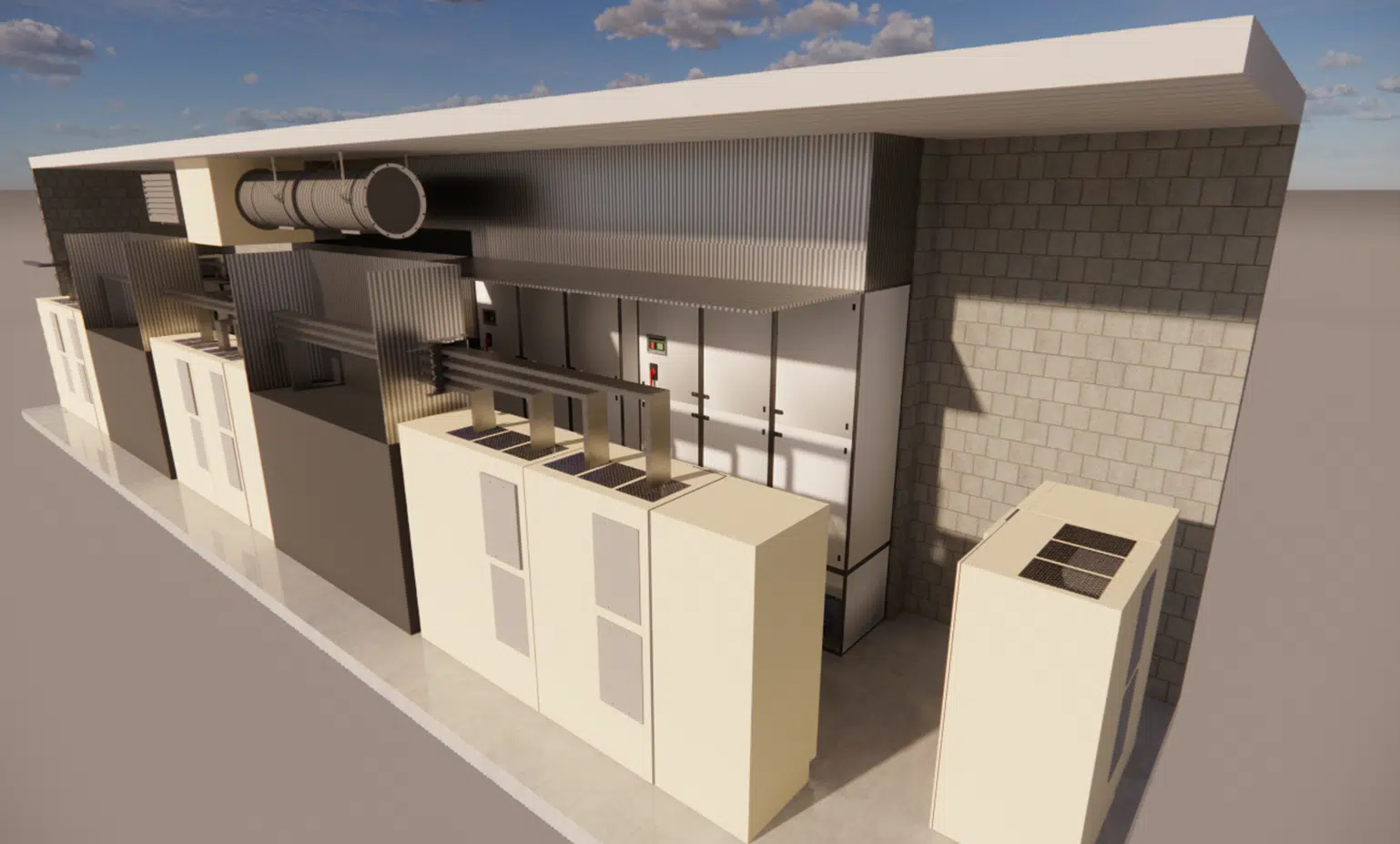
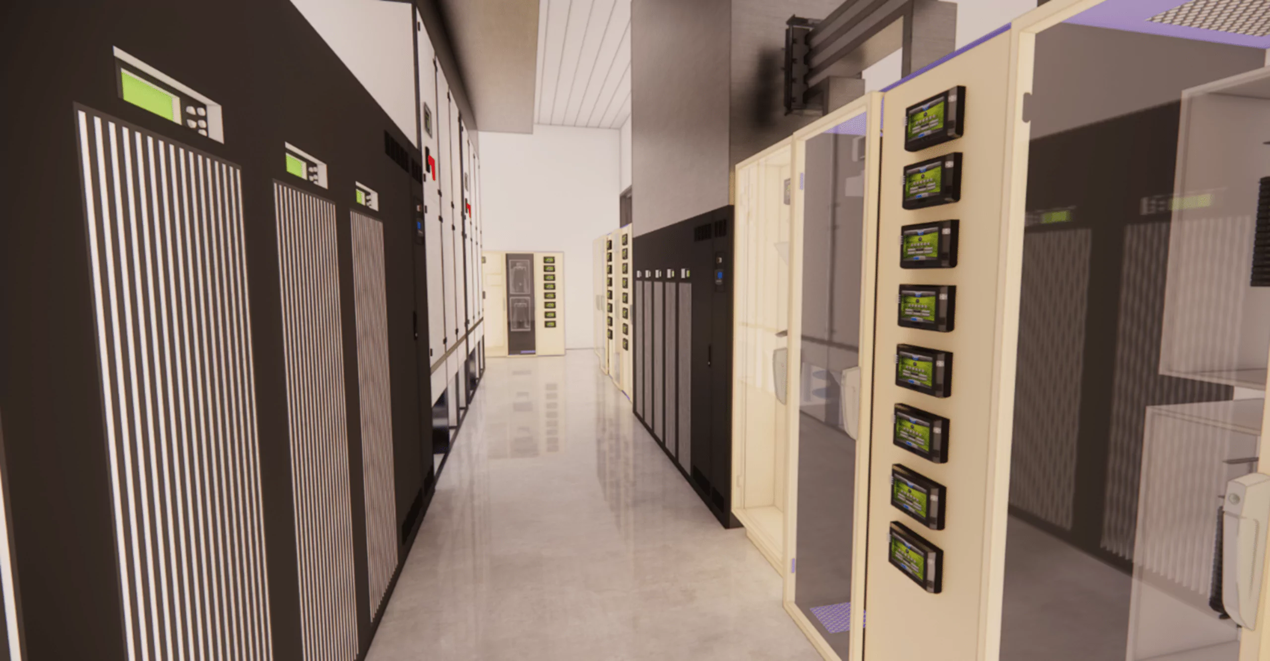
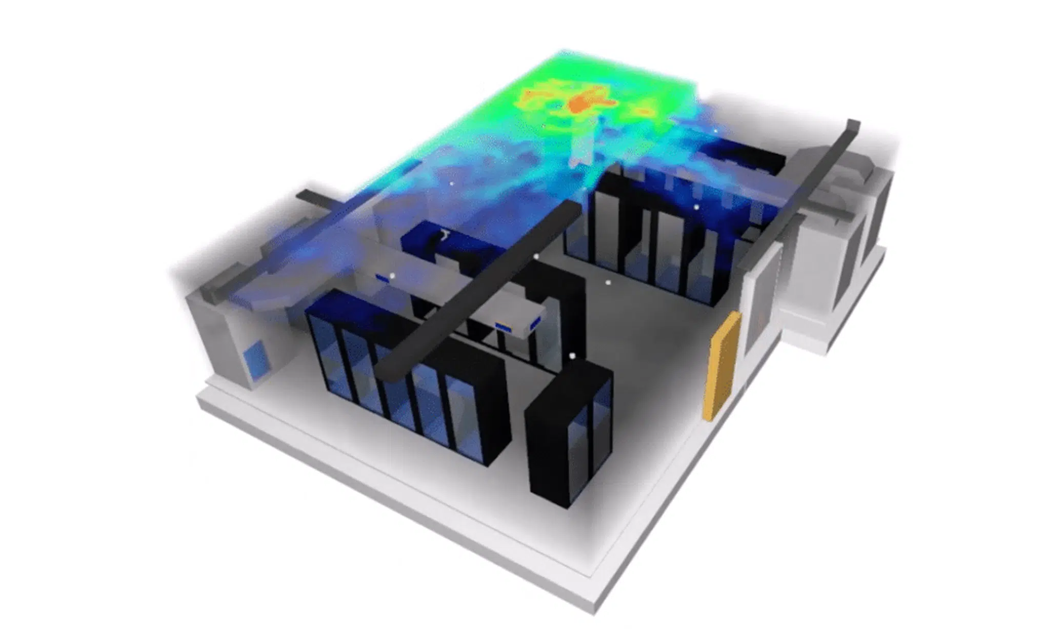
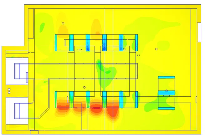
During our simulations on the existing configuration of the technical rooms, excessively high temperatures were observed at the fresh-air intakes of the systems. These high temperatures are caused mainly by short-circuiting phenomena, where the hot air is recycled instead of being removed efficiently.
In addition, the presence of hot spots, zones where heat dissipation is insufficient, was identified, which can lead to risks of equipment overheating. A new design is then necessary to optimise air circulation, avoid the short-circuiting phenomena and improve thermal dissipation.
A phenomenon where the hot air rejected by the equipment is drawn back in instead of being removed. It raises the air-intake temperature, reduces cooling efficiency and encourages the appearance of hot spots.
New designs suited to each room were proposed to avoid the short-circuiting phenomenon and reduce the excessive temperatures:
Ducting of the heat releases to better channel and remove the heat.
Full enclosure between the upper and lower parts to compartmentalise the hot and cold air masses.
Raising of the CRAH intakes for better capture of the heat-laden air.
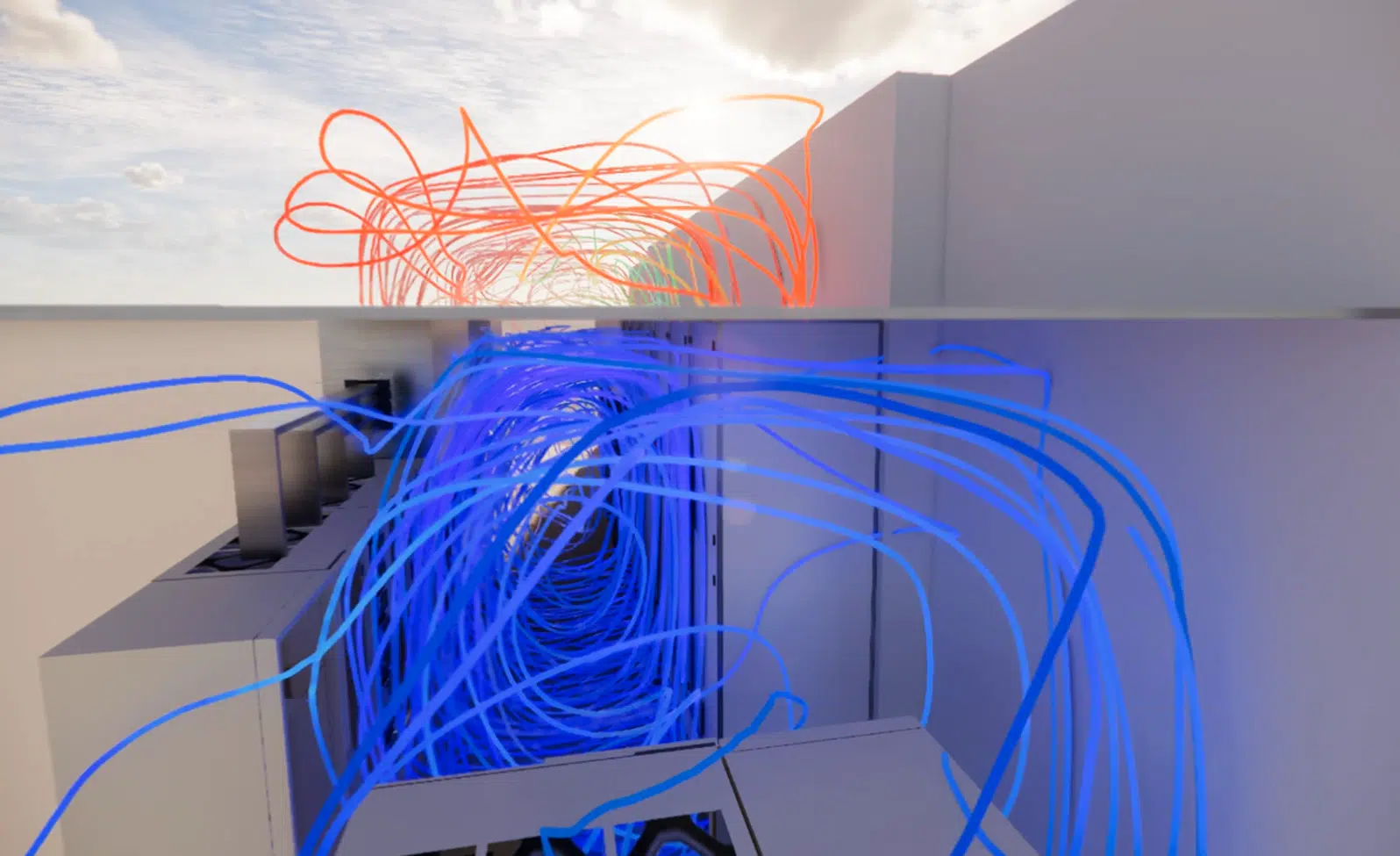
These new designs were submitted to advanced CFD simulations to assess their effectiveness. The results are very encouraging: they clearly show that the new designs make it possible to avoid the short-circuiting phenomenon and to reduce the temperatures at the fresh-air intakes of the systems. The temperatures could be lowered by 5 °C, which greatly contributes to guaranteeing optimal operating conditions and to reducing the risks of overheating in the technical rooms of the data center.
Key takeaway. The bespoke designs (STS ducting, UPS enclosure, raising of the CRAH intakes on the transformer side) eliminate the short-circuiting and lower the intake temperatures by 5 °C.
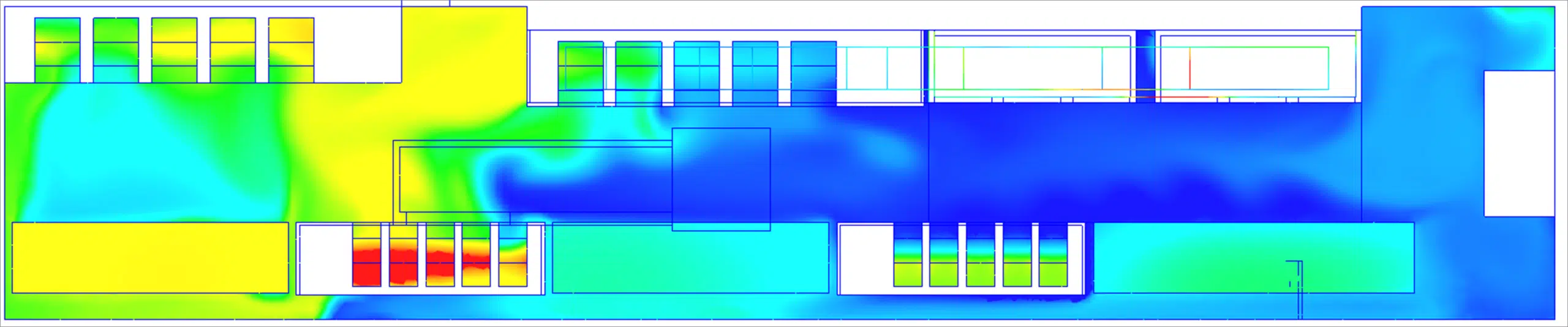
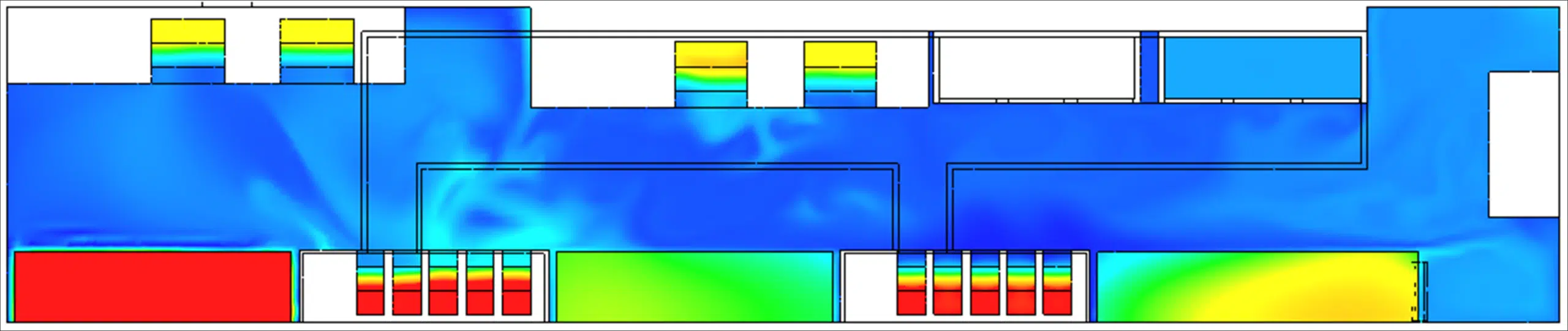
A meticulous redundancy analysis was carried out in the technical rooms in order to ensure unrivalled reliability of the cooling systems. For this, two CRAH units are installed in each room, operating in parallel for optimal operational redundancy. This approach makes it possible to maintain sufficient cooling capacity even in the event of a failure of one of the units.
An air-handling unit of a technical room that draws in the hot air, cools it and then blows it back. Its flow rates and the height of its intakes govern the capture of the heat and the uniformity of the temperatures.
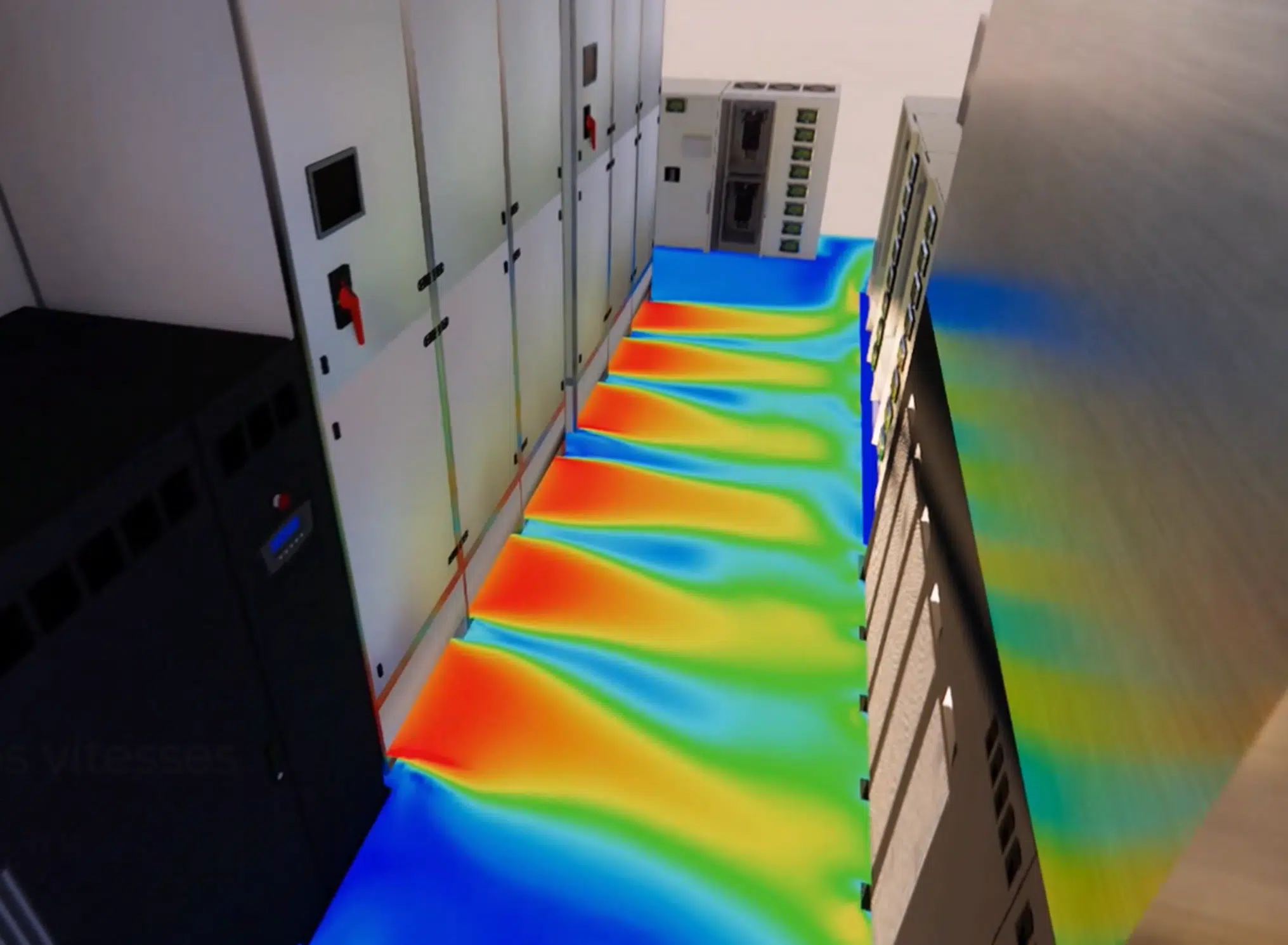
In order to validate the effectiveness of this redundancy, detailed simulations were carried out considering the deactivation of one CRAH unit. The results showed that even with one CRAH shut down, the temperature in the technical rooms remains within a suitable range, with no risk of overheating. This demonstration highlights the effectiveness of the redundancy put in place.
At EOLIOS, the crucial importance of redundancy in critical environments such as data centers is always taken into account. Expertise in CFD simulation makes it possible to design robust and reliable cooling solutions, thereby guaranteeing continuous availability of the equipment even in the event of a failure of one unit.
The principle of installing a backup cooling unit in addition to the strict minimum, so that a failure or maintenance does not compromise the cooling. CFD checks the temperature behaviour with one unit shut down.
Key takeaway. Testing the redundancy by calculation, with one CRAH shut down, proves the availability of the cooling before the real incident rather than assuming it.
Short-circuiting, bespoke designs and CRAH redundancy: the answers to the questions operators and designers ask before a thermal CFD study.
Unlike server rooms with hot and cold aisles, each technical room is unique and standardised solutions are often unsuitable there. CFD models air circulation, dissipation and temperature distribution to identify the hot zones and design bespoke cooling, as on our cooling optimisation of a data center.
It is the recirculation of the hot air rejected by the equipment towards its own fresh-air intakes. It raises the intake temperatures and creates hot spots; eliminating it is the primary goal of the redesign.
From the architectural plans (dimensions, layout) and site visits (measurements of the cooling systems, grilles, obstacles). Each element receives its physical properties: thermal conductivity, heat releases and air-conditioning performance.
Ducting of the heat releases (STS), full enclosure (UPS) and raising of the CRAH intakes (transformers) eliminate the short-circuiting and lower the intake temperatures by 5 °C.
It simulates the shutdown of one of the two CRAH units per room: the temperature stays within a suitable range with no risk of overheating, which guarantees continuous availability even in the event of a failure.
Explore our expertise, projects and technical papers to go beyond the FAQ.
Thermal CFD study of the technical rooms (UPS, STS, transformers): detection of short-circuiting and hot spots, bespoke designs (enclosure, ducting, CRAH raising) and validation of the redundancy.
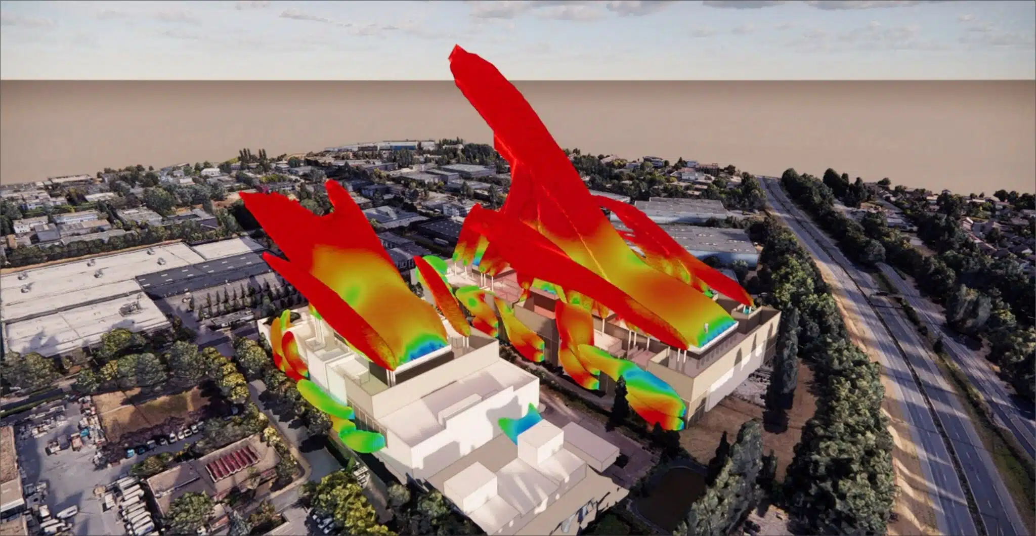 Digital twinData center study – Data Hall and UPS rooms
 Smoke controlSmoke-control engineering in a data center
 HyperscaleExternal & internal CFD – Hyperscale Data Center
 OptimisationCFD optimisation – Data Center
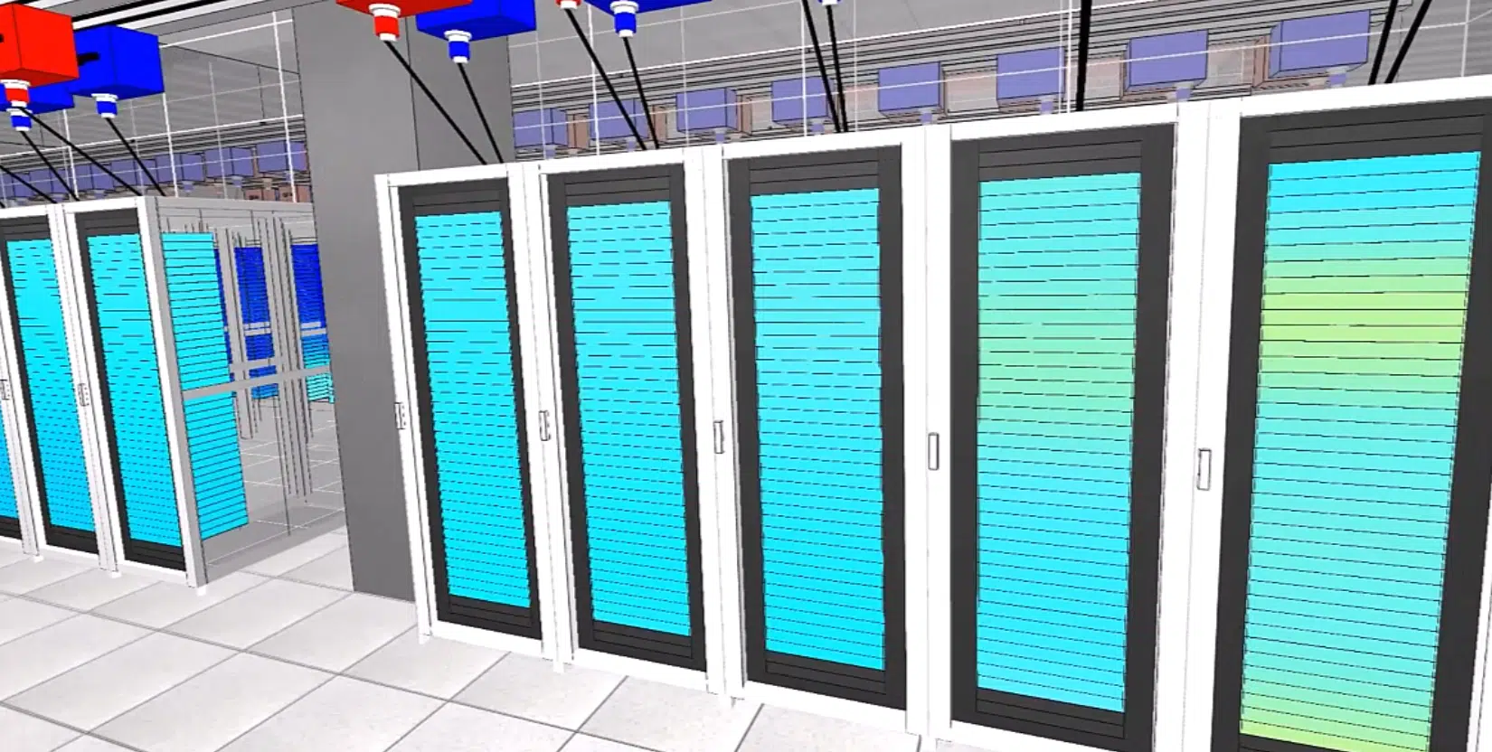 InternalData Center – DC28 – Internal
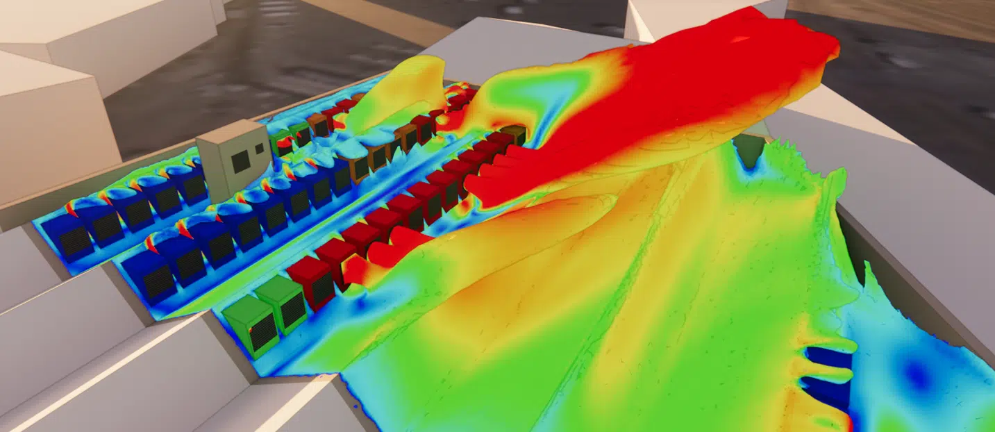 CoolingCooling optimisation – Data Center
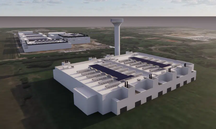 ExternalData Centers – DC15.1 & DC15.2 – External
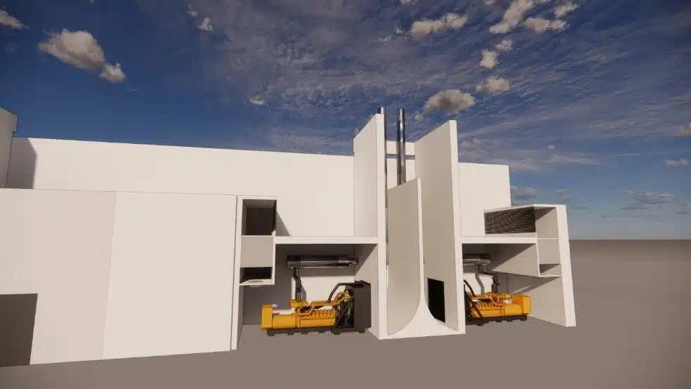 ExternalData Center – PA 22 – External
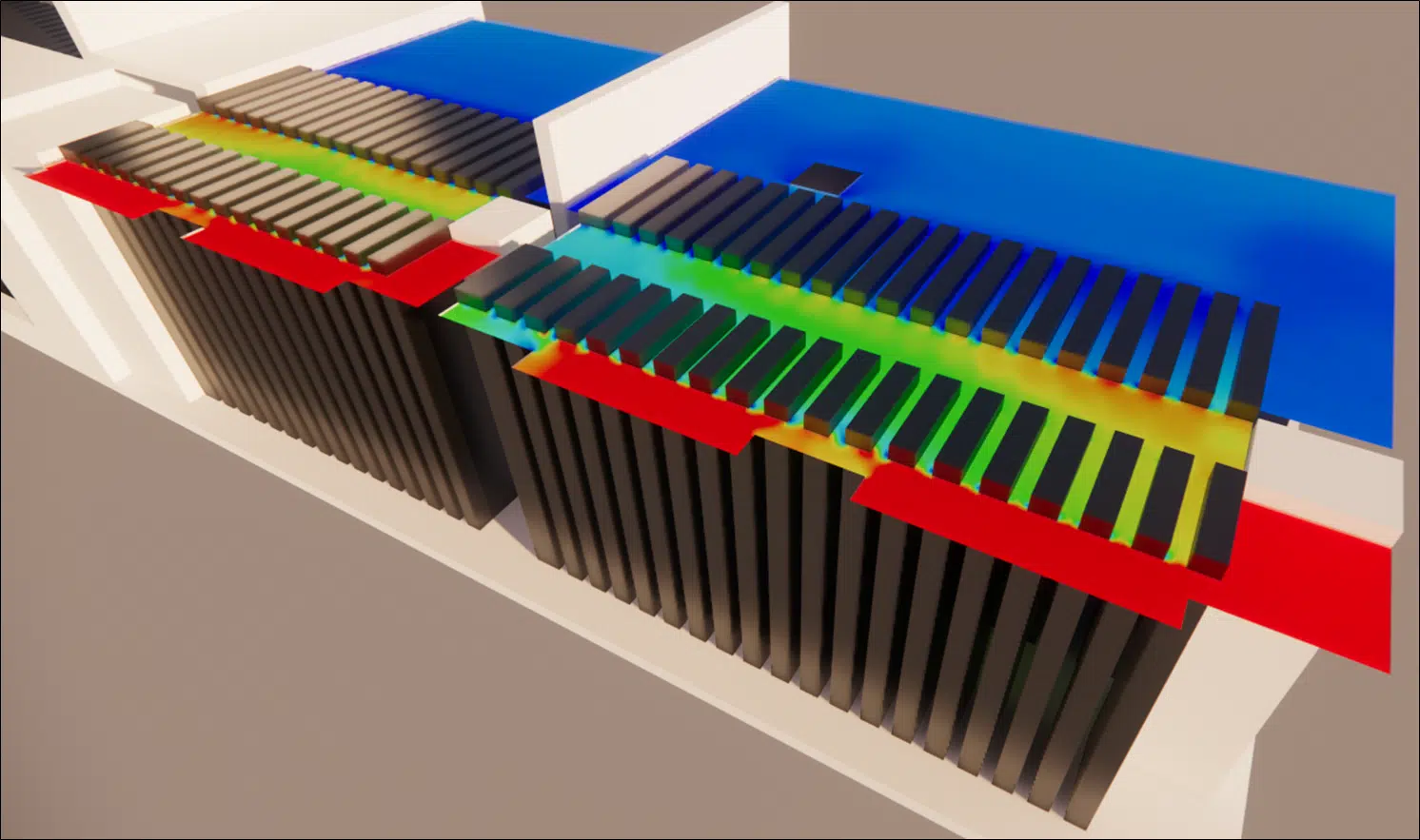 GeneratorPressure-loss study – Generator – Data center
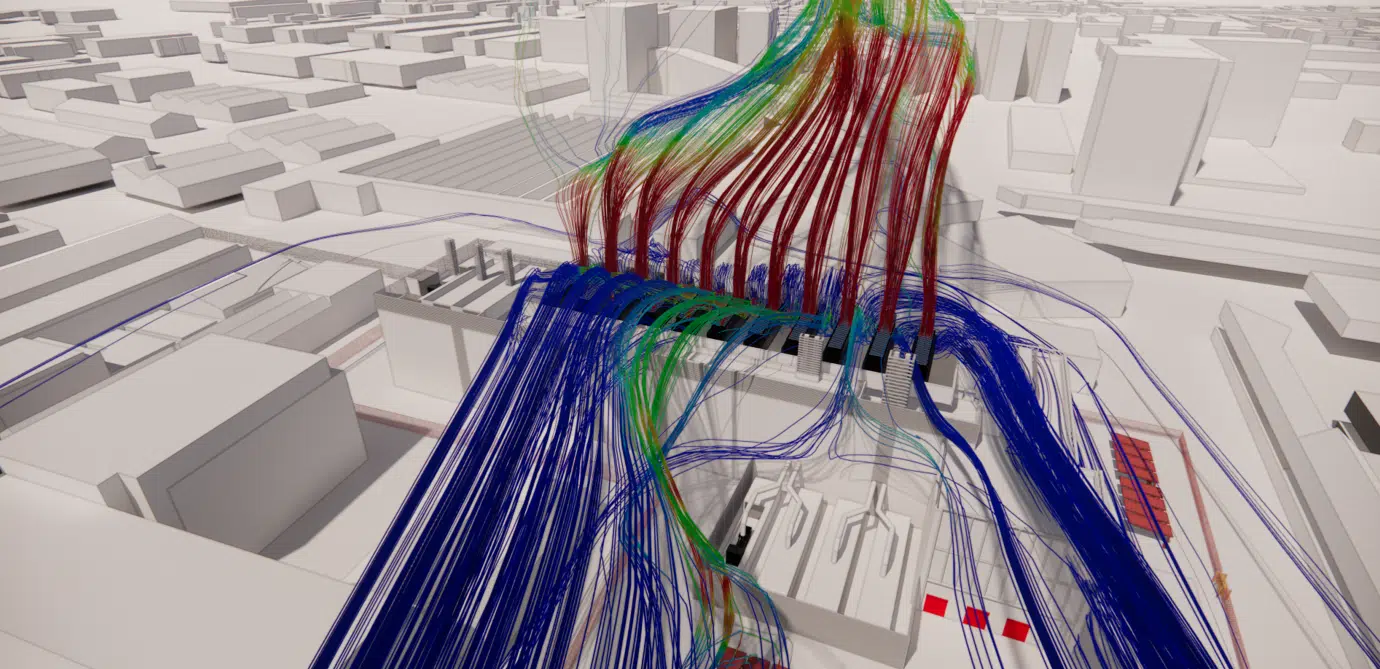 ExternalData Center – Paris
 FireData Center – NOVEC gas
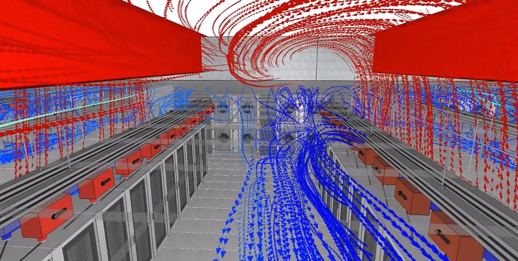 InternalData center – DC17 – Internal
 ExternalData center – D14 – External
 ExternalData center – DC25 & DC26 – External
 InternalData Center – DC10 – Internal
 InternalData center – DC25 – Internal
ExternalData Center – DC25 & DC26 – External
InternalData center – DC25 – Internal
ExternalData Center – DC25 & DC26 – External