
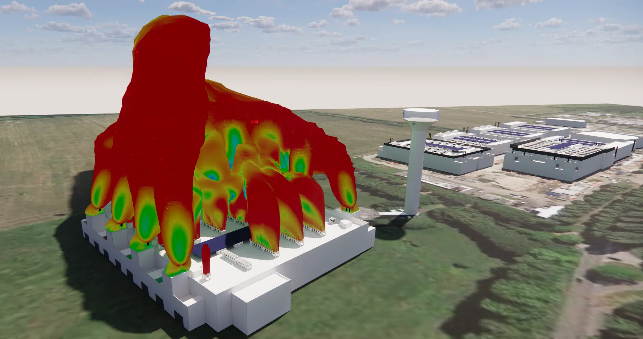
External CFD study of the thermal plumes of a data center in Milan: generator discharge, impact on adjacent buildings and rooftop hot zones.
EOLIOS Engineering provided an overview of the thermal-airflow conditions of the thermal plume of a data center and of the generators of the adjacent data centers, in order to secure the rooftop cooling.
The essentials. External CFD study of a data center in Milan: the exhaust plume of the generators is set against the rooftop systems, with a wind profile reconstructed like a wind tunnel over a 300 m urban periphery. Result: the plumes have a far-reaching influence, but there is no major short-circuit near the discharges. The very high installation density does, however, create a few rooftop hot zones, corrected by optimising the layout.
This study examines the exhaust plume of a series of generators against the rooftop systems of a data center. The aim: to determine whether the exhaust of the systems can contaminate the supply air of the various equipment and to measure its impact on the adjacent buildings.
To this end, our engineers simulate by numerical CFD calculation the thermal-airflow behaviour of the various phenomena occurring outside the model.
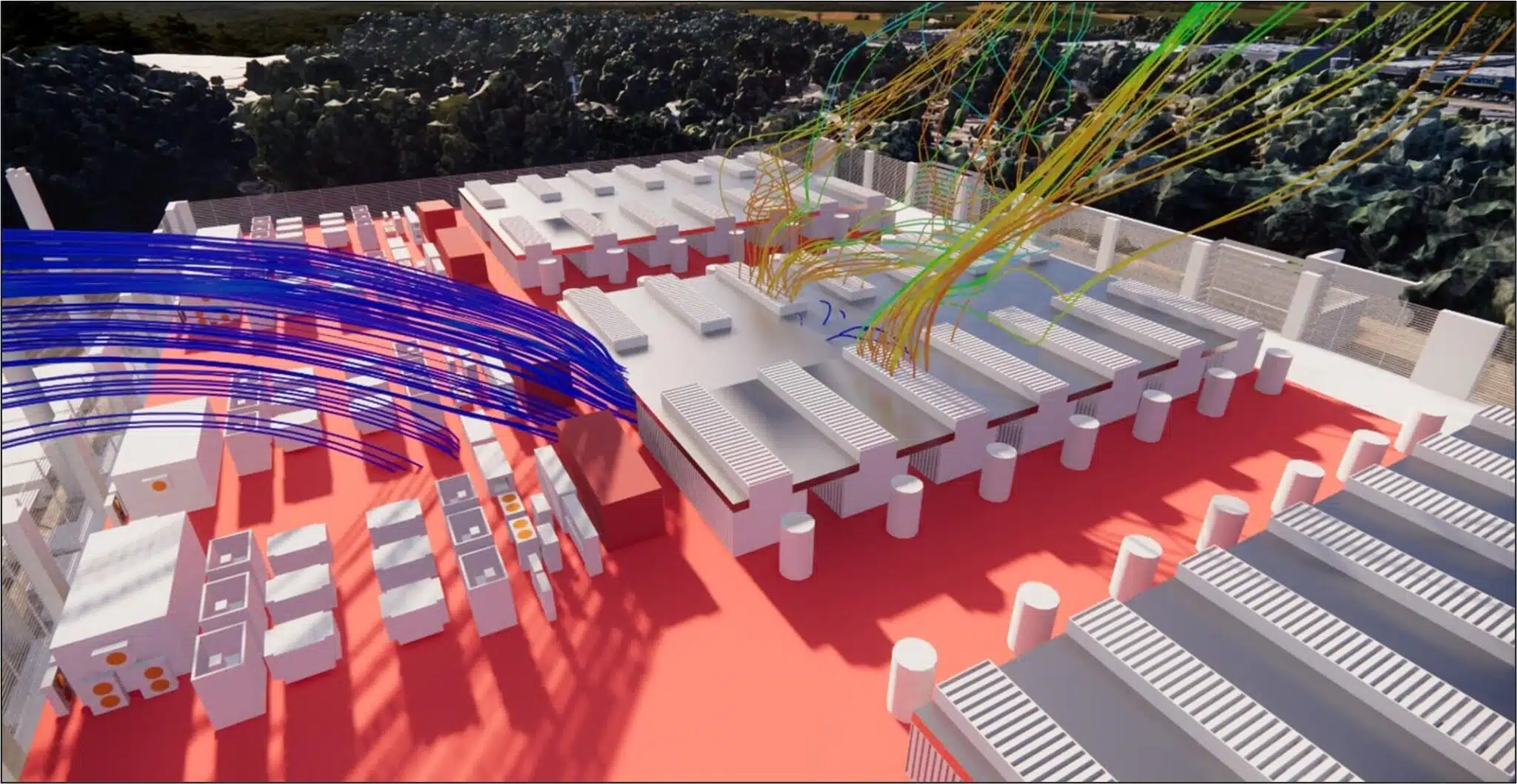
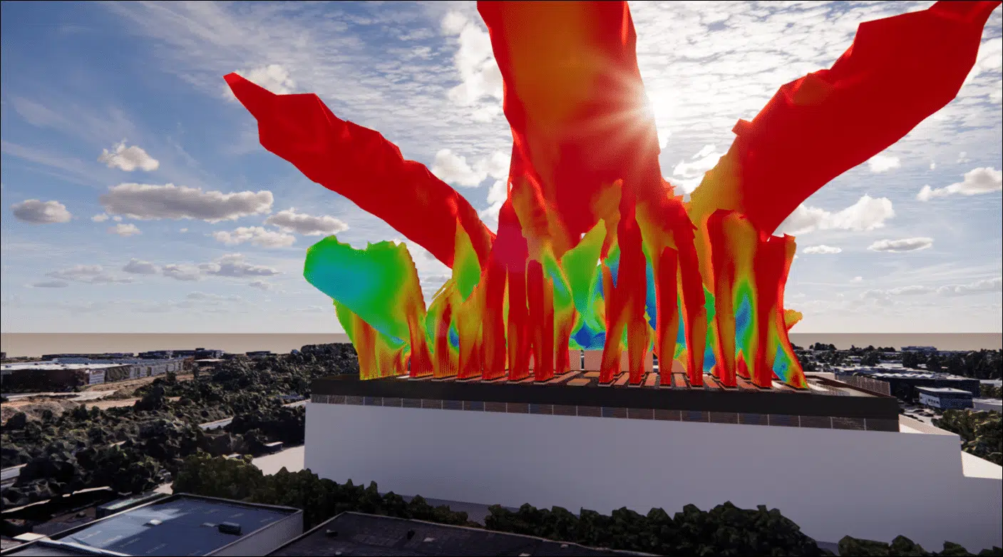
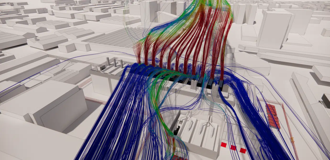
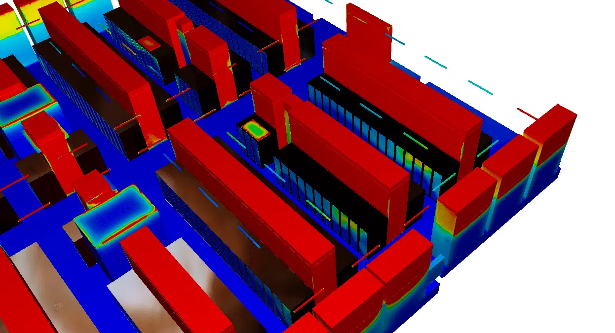
Volume of hot air rejected by a source (generator, rooftop system) that rises and deforms under the effect of its buoyancy and the wind. Its trajectory governs the risk of re-ingestion by neighbouring systems and the impact on the surroundings.
In CFD modelling, the shape of the vertical wind-speed profile is decisive. It depends above all on the surface roughness, i.e. the slowing effect of the buildings, trees and obstacles that oppose the flow at the surface. Throughout the thickness of the atmospheric boundary layer, the wind speed increases as one moves away from the ground.
To account for wind shear, the study uses a methodology similar to a physical wind tunnel: the urban environment is reconstructed over a 300 m periphery around the site, with a site-dependent speed profile.
The region of the atmosphere near the ground where the wind is slowed and sheared by the terrain and the built environment. Reproducing it faithfully governs the realism of the wind speeds applied to the model.
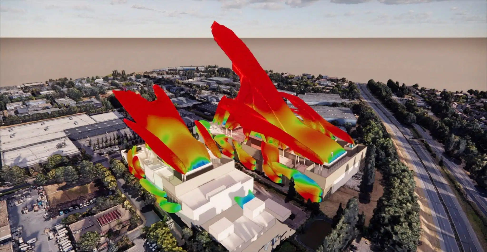
The CFD simulation shows that the thermal plumes have a far-reaching influence beyond their emission zone. But overall, close to the discharges, there is no major short-circuit likely to stop the systems: the supply air is correctly drawn in at low level and discharged at altitude.
These conclusions were a valuable aid to the design teams, in verifying that the layout of the cooling systems did not create any recirculation zone, including with respect to the urban heat-island effects on the neighbouring buildings.
Re-ingestion, by the cooling systems, of part of the hot air they have just rejected. It raises the intake temperature and reduces the available power; its absence confirms the correct layout of the equipment.
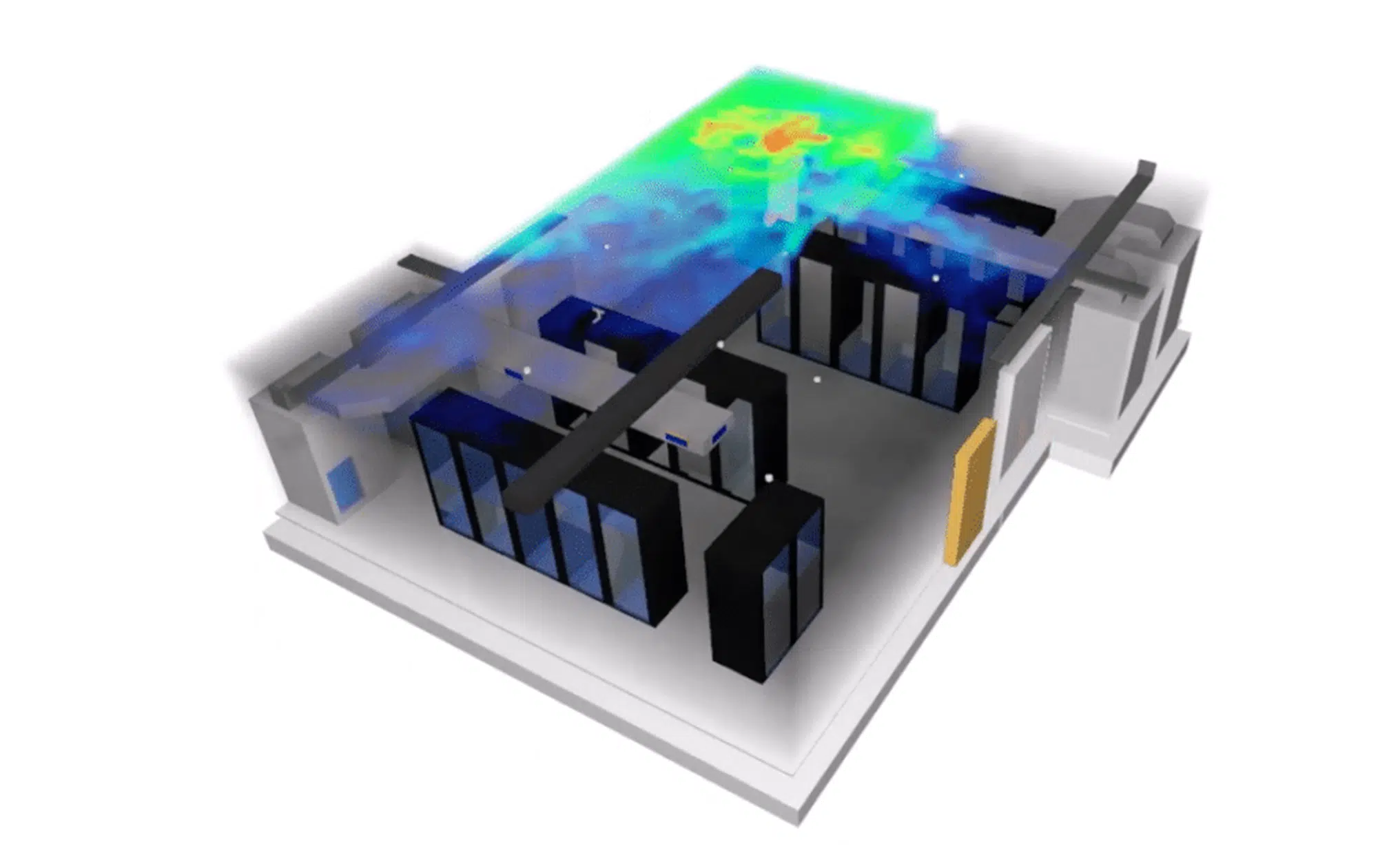
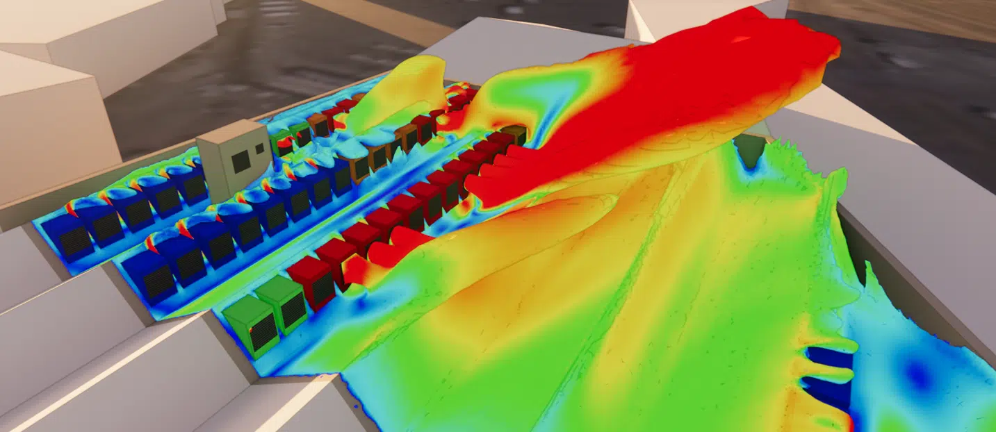
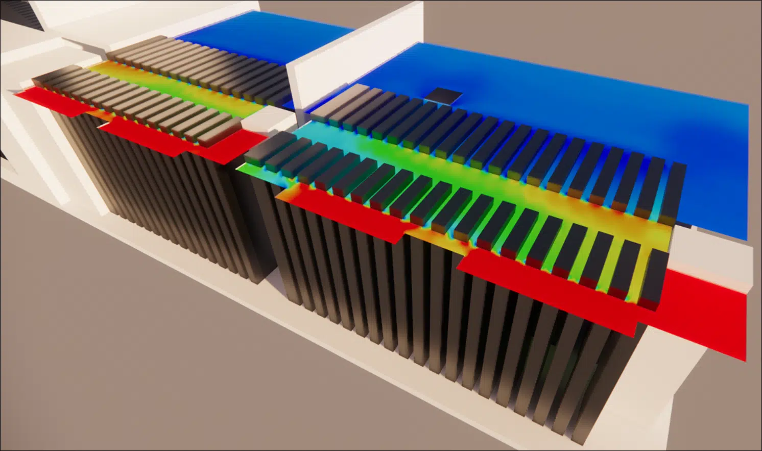
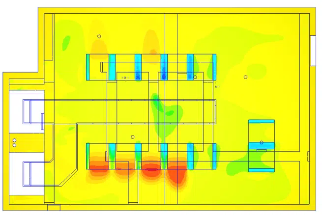
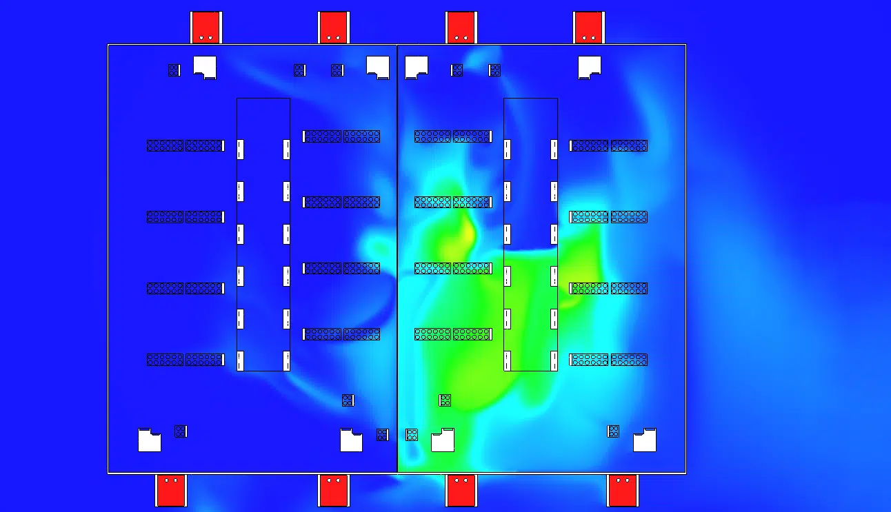
The simulation, run on the model in its entirety, allows the simultaneous analysis of many phenomena. It shows that the very high installation density produces a few rooftop hot zones: the most exposed systems, in the centre, are liable to draw in air beyond their operating range, an issue close to internal overheating.
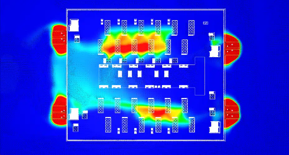
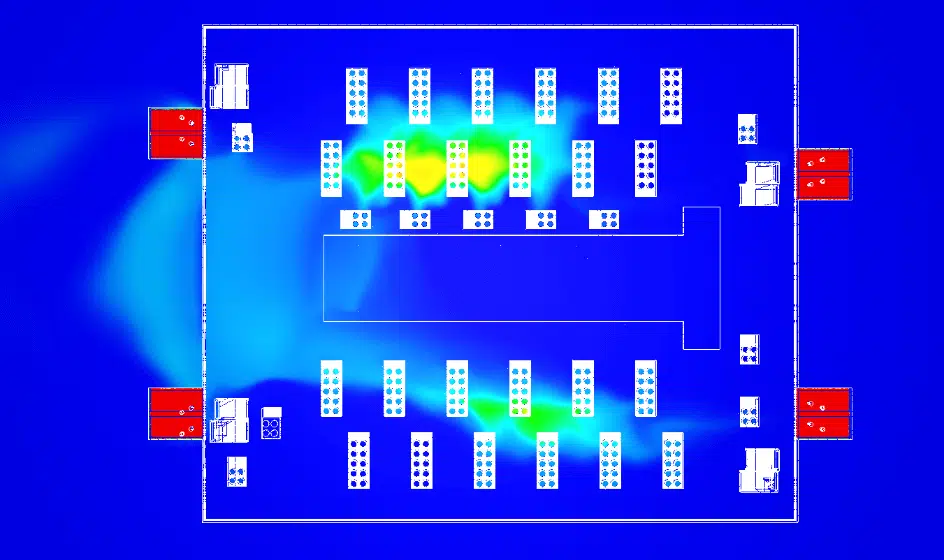
Comparing the temperature plans before and after shows the effect of an optimised layout of the cooling systems: the hot-air intakes are brought back within the admissible ranges.
Key takeaway. Even without a major short-circuit, a high equipment density generates localised hot zones. CFD, carried out from the design stage, validates the layout of the systems and secures their operating range.
Thanks to the conclusions of the study, suitable solutions were proposed to the design teams to solve these issues. CFD simulation makes it possible to analyse, verify and correct potential errors from the design stage: a fast, precise method that saves time and costs while guaranteeing concrete, reliable results. Integrating CFD from the design phase is the guarantee of avoiding future problems.
Know-how: external CFD simulation for data centersPlume, wind profile and rooftop hot zones: answers to the questions raised by operators and design teams.
To examine the exhaust plume of a series of generators against the rooftop systems, determine whether this exhaust can contaminate the equipment supply air, and measure its impact on the adjacent buildings, as on our sister PA 22 data center project.
The vertical wind-speed profile depends on the surface roughness (buildings, trees, obstacles). By reproducing the urban environment over 300 m around the site with a site-dependent speed profile, the study recreates wind shear as in a physical wind tunnel.
The thermal plumes have a far-reaching influence beyond their emission zone, but close to the discharges there is no major short-circuit likely to stop the systems: the supply air is correctly drawn in at low level and discharged at altitude.
The very high installation density produces a few hot zones on the roof. The most exposed systems, in the centre, are liable to draw in air beyond their operating range, which optimising the layout corrects.
CFD simulation makes it possible to analyse, verify and correct potential errors from the design stage. Fast and precise, it saves time and costs while guaranteeing reliable results before construction.
Explore our expertise, projects and technical papers to go further than the FAQ.
External CFD study of the D14 data center in Milan: thermal plume of the generators at 50 °C, influence on the rooftop systems and on the adjacent buildings. The simulation confirms the absence of a major short-circuit and locates the hot zones linked to the installation density.
 Digital twinData center study – Data Hall and UPS rooms
 Smoke controlSmoke-control engineering in a data center
 HyperscaleExternal & internal CFD – Hyperscale Data Center
 OptimisationCFD optimisation – Data Center
 InternalData Center – DC28 – Internal
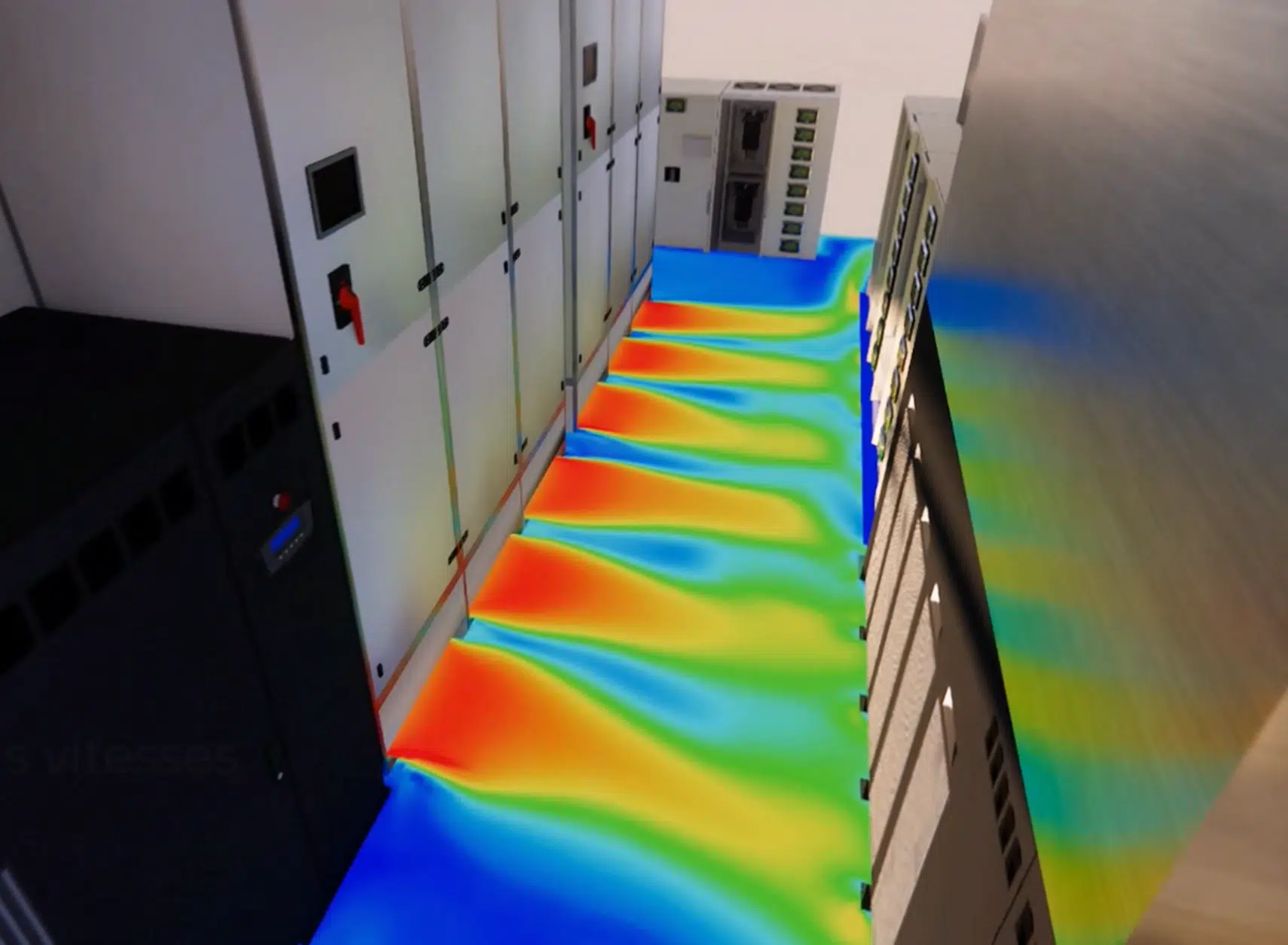 Technical roomsTechnical rooms – Data Center
 CoolingCooling optimisation – Data Center
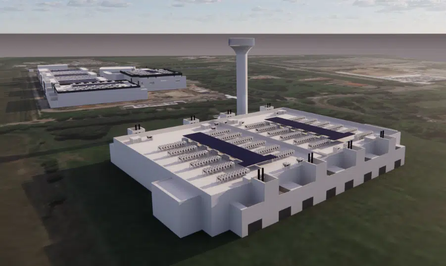 ExternalData Centers – DC15.1 & DC15.2 – External
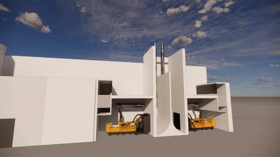 ExternalData Center – PA 22 – External
 GeneratorPressure-loss study – Generator – Data center
 ExternalData Center – Paris
 FireData Center – NOVEC gas
 InternalData center – DC17 – Internal
 ExternalData center – DC25 & DC26 – External
 InternalData Center – DC10 – Internal
 InternalData center – DC25 – Internal
ExternalData Center – DC25 & DC26 – External
InternalData center – DC25 – Internal
ExternalData Center – DC25 & DC26 – External