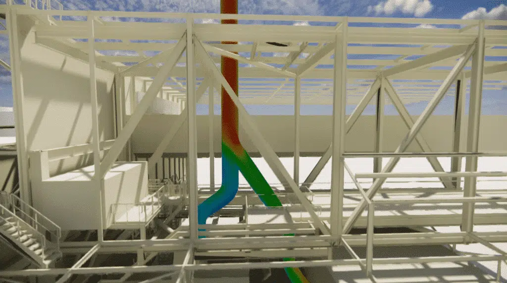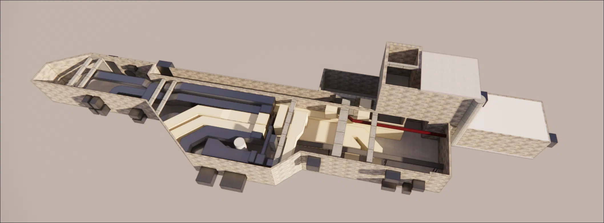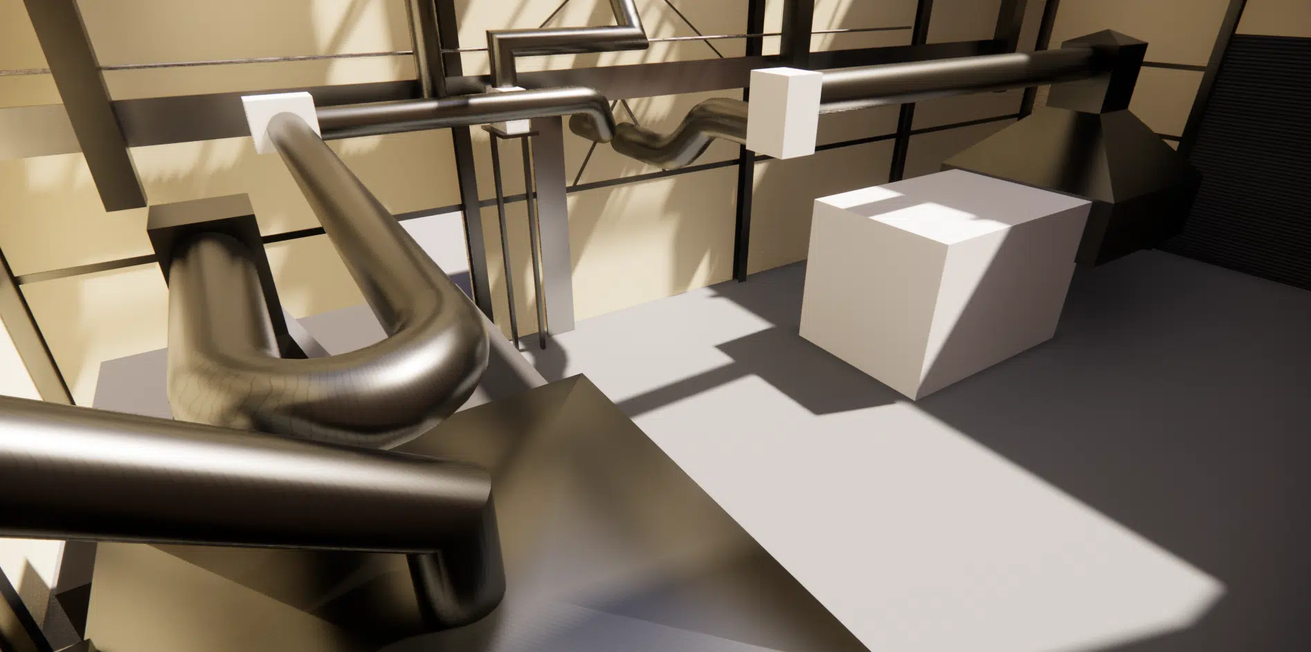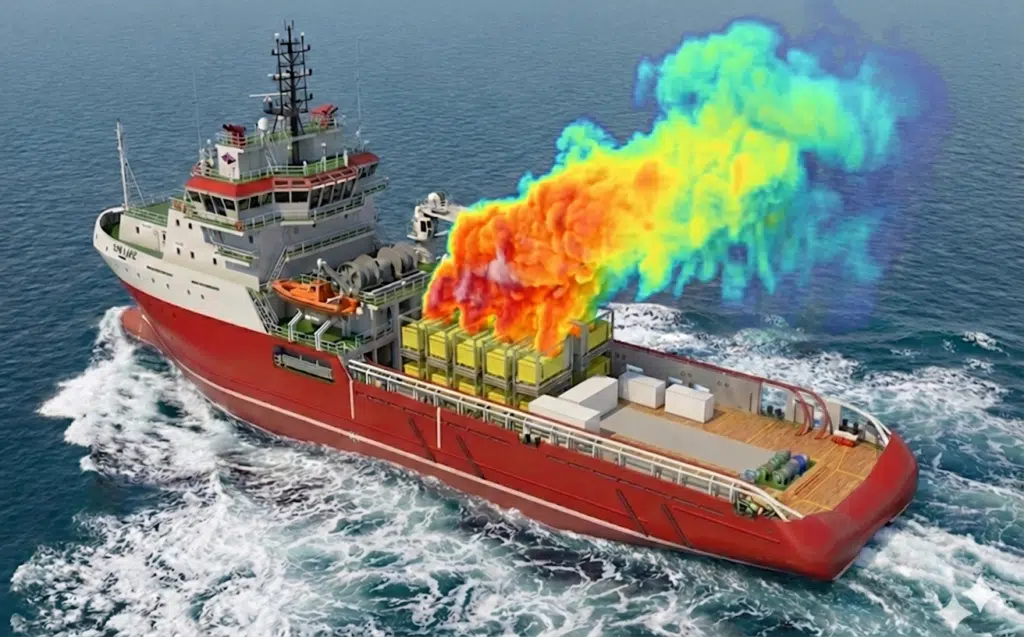
Analysis of the heat rejection of 18 stacked diesel compressors on the deck of an offshore vessel in the Baltic Sea, to ensure the reliability of the installations and the comfort of the technicians.
EOLIOS is an expert in the optimisation of complex airflows and wind comfort. As part of a large-scale industrial project, we were asked to analyse the thermo-airflow behaviour of a massive compression system installed on the deck of an offshore vessel operating in the Baltic Sea. The stakes were high: simulating the heat exchanges of 18 stacked diesel compressors to guarantee the reliability of the technical installations and the safety of operations.
In brief. On the deck of an offshore vessel in the Baltic Sea, 18 diesel compressors of 224 kW each reject air at close to 65 °C. Despite a 6 m/s head wind, the naval architecture traps the heat: the CFD simulations reveal hot-air recirculations, heat bubbles reaching 47 °C in the intervention zones and leaks of 30% on the extraction systems. The solution validated by EOLIOS cuts these leaks to 3% and secures both the machines and the technicians.
EOLIOS is a leader in CFD simulation for your processes. Our studies draw on the experience of real-world measurement campaigns and around a hundred sites simulated worldwide.
In a maritime environment subject to high heat emissions, standard ventilation solutions reach their limits. Through an analysis combining 3D modelling and CFD simulation, EOLIOS studied the real behaviour of the airflows around 18 diesel compressors and proposed concrete solutions to optimise the extraction of the rejected heat, improve thermal comfort and guarantee the reliability of the installations in the production zones.
The mission was built around four objectives:
Model the vessel, its aerodynamic masks and the 18 compressors under their real weather conditions.
Quantify the suction temperatures of the machines and the ambient temperatures in the intervention zones.
Identify the recirculation and stagnation mechanisms responsible for the overheating.
Validate a heat-extraction solution guaranteeing service continuity and the safety of the technicians.
To meet this challenge, our engineers developed a complete digital twin of the vessel and its technical installations. Faithfully reproducing the complex geometry of the structures and the layout of the equipment on the deck is crucial to capture the wake and recirculation phenomena.
The “digital twin” is the 3D virtual replica of a real installation: geometry, heat sources, air inlets and outlets, weather conditions. It serves as the basis for CFD simulation to test the behaviour of the installation in scenarios impossible to reproduce on site: extreme winds, full load, design variants.
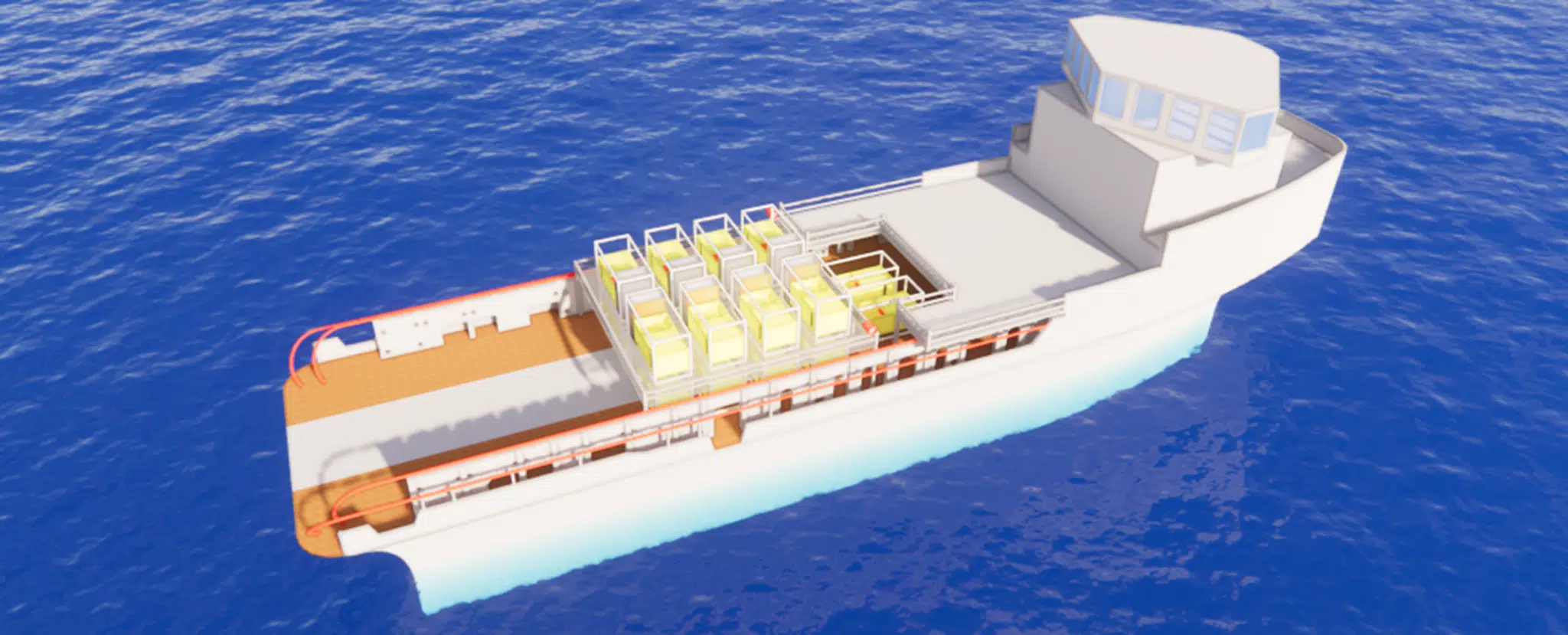
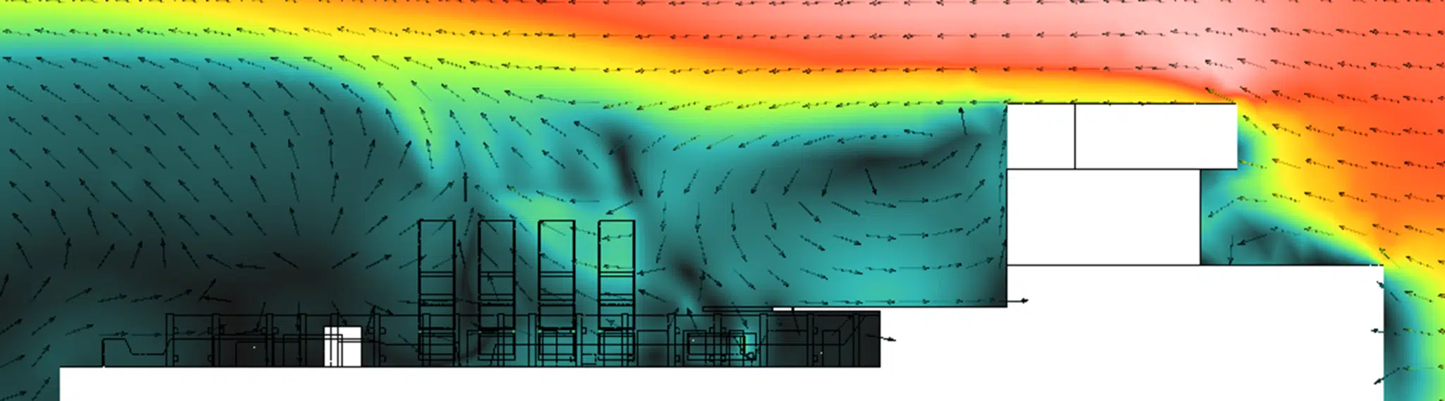
The model incorporated intense weather conditions specific to the Baltic Sea, with a sustained head wind of 6 m/s coupled with a high outside temperature. The main difficulty of this study lay in accurately modelling these unstable edge conditions, where the incident airflow meets a naval architecture generating multiple zones of stagnation and aerodynamic separation. These zones limit the air renewal around the technical installations. In the absence of forced, directed ventilation, these zones become thermal traps where the rejected heat stagnates, locally raising the ambient temperature regardless of the strength of the outside wind.
Packing 18 compressors into a confined space represents a colossal thermal load. Each unit develops a total power of 224 kW, generating a massive heat flow that must be extracted continuously to preserve the integrity of the system. In operation, the air is expelled at an outlet temperature approaching 65 °C, creating a genuine heat source at the heart of the vessel. Without rigorous flow management, the risk of overheating is immediate: the simulations revealed that the suction temperatures could quickly reach the critical threshold of the systems, threatening the integrity of the machines and service continuity.
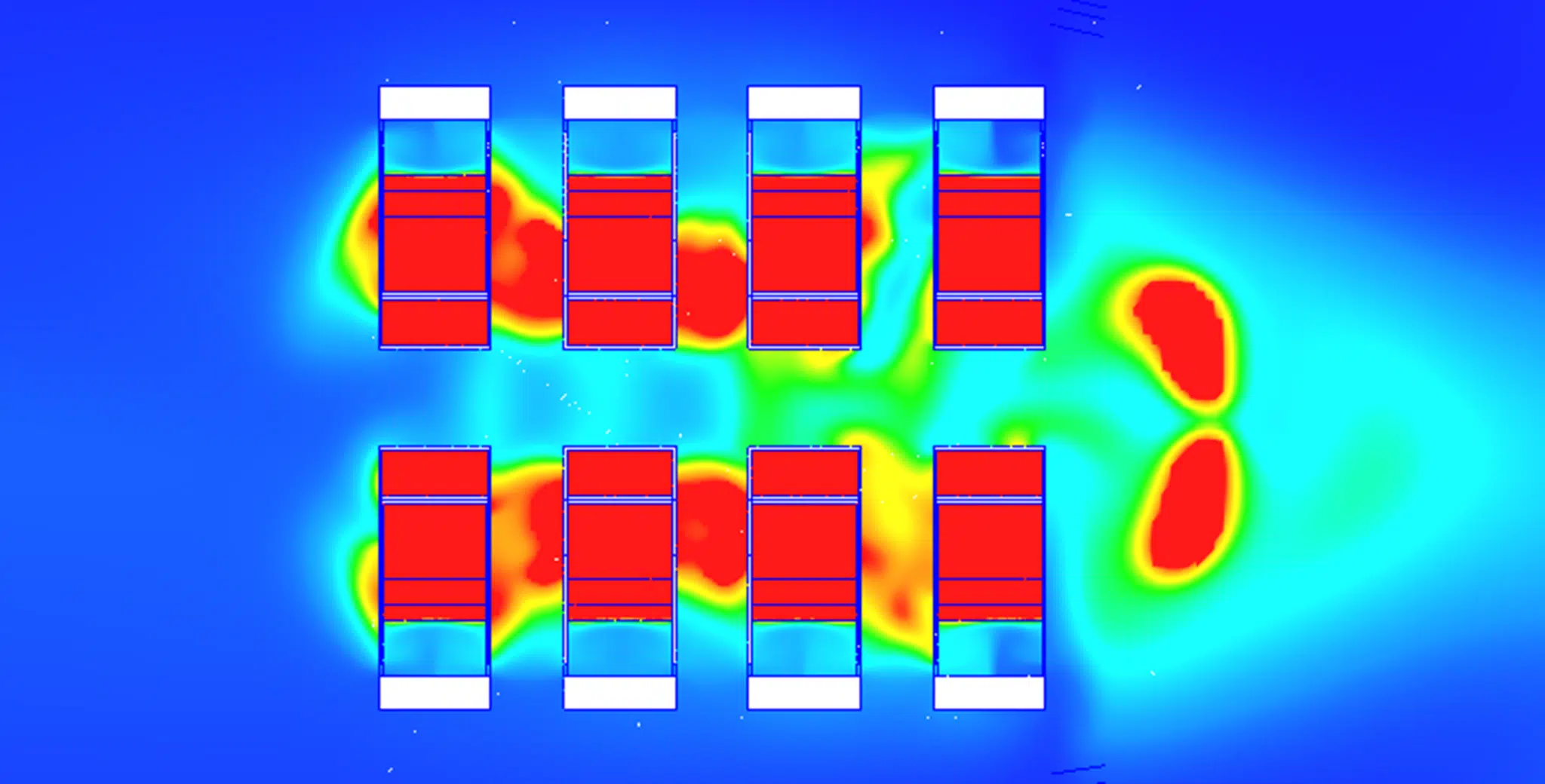
“Recirculation” occurs when part of the hot air rejected by a machine is drawn back in, by the machine itself or by a neighbouring unit, instead of being extracted. The intake temperature then rises above the outside temperature, degrading the efficiency and potentially triggering the equipment's safety shutdown.
Our engineers identified two distinct physical phenomena degrading the performance:
Direct recirculations (short loops): the hot air rejected at the outlet of some compressors was immediately drawn back in by the air intakes of the neighbouring units.
Indirect recirculations (ambient heating): the heat stagnating around the structure created an overall rise in the temperature of the surrounding air, “polluting” the fresh air before it was even drawn in by the systems.
These recirculation phenomena stem directly from a structural confinement where the compact arrangement of the compressors, coupled with the presence of massive architectural obstacles, traps the air on the deck. This configuration hinders the circulation of the flows and prevents natural convection from playing its role as a thermal regulator, creating zones of stagnation where the heat accumulates without being able to escape. In the absence of an effective fresh-air sweep, the vessel's architecture ends up acting as a trap, forcing the re-intake of hot air and thereby degrading the overall performance of the installation.
The comfort of the technicians and maintenance staff was also a crucial point for the client, beyond the sole issues of the equipment's thermal performance. Human interventions on the deck require ambient conditions compatible with sometimes lengthy maintenance operations, carried out in the immediate vicinity of the heat sources.
The physics of the flows shows that, in the absence of an optimised solution, stagnant heat creates “heat bubbles” reaching up to 47 °C, making interventions on the deck extremely arduous, even dangerous. These thermal accumulations appear mainly in the zones of low air mixing, where the hot plumes from the equipment tend to concentrate without being properly extracted.
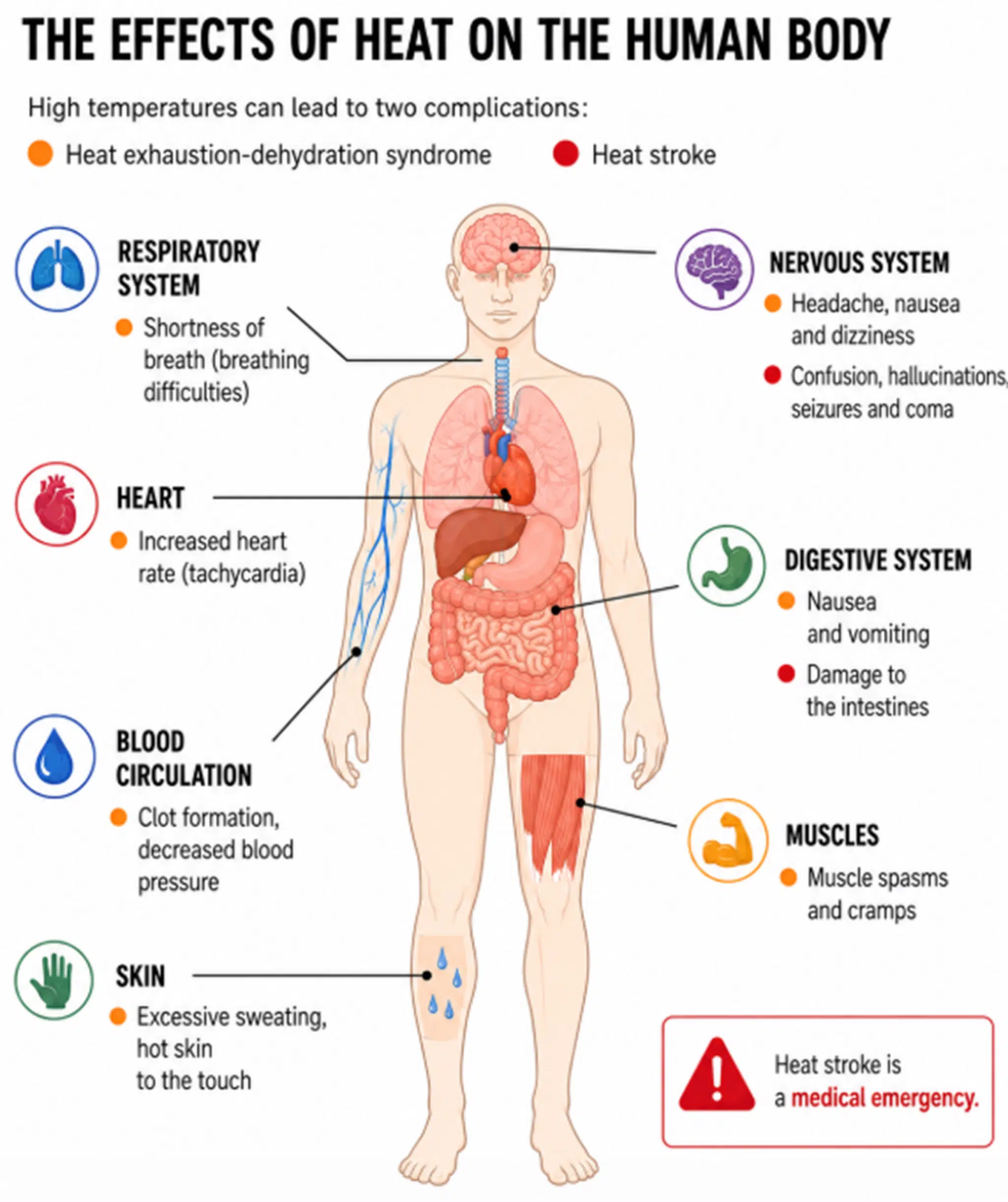
An occupational-safety issue. At 47 °C the body can no longer shed its own heat: sweating becomes ineffective, the heart rate climbs and the risk of heatstroke appears within tens of minutes. A prolonged maintenance intervention in such a thermal bubble is not merely uncomfortable, it is dangerous.
The study focused on managing the rejected flows to channel the hot air away from the sensitive zones. Our first analyses revealed a major technical challenge: hot-air leaks amounting to 30 % at the junctions of the extraction systems, which cancelled out part of the benefits and maintained a local overheating.
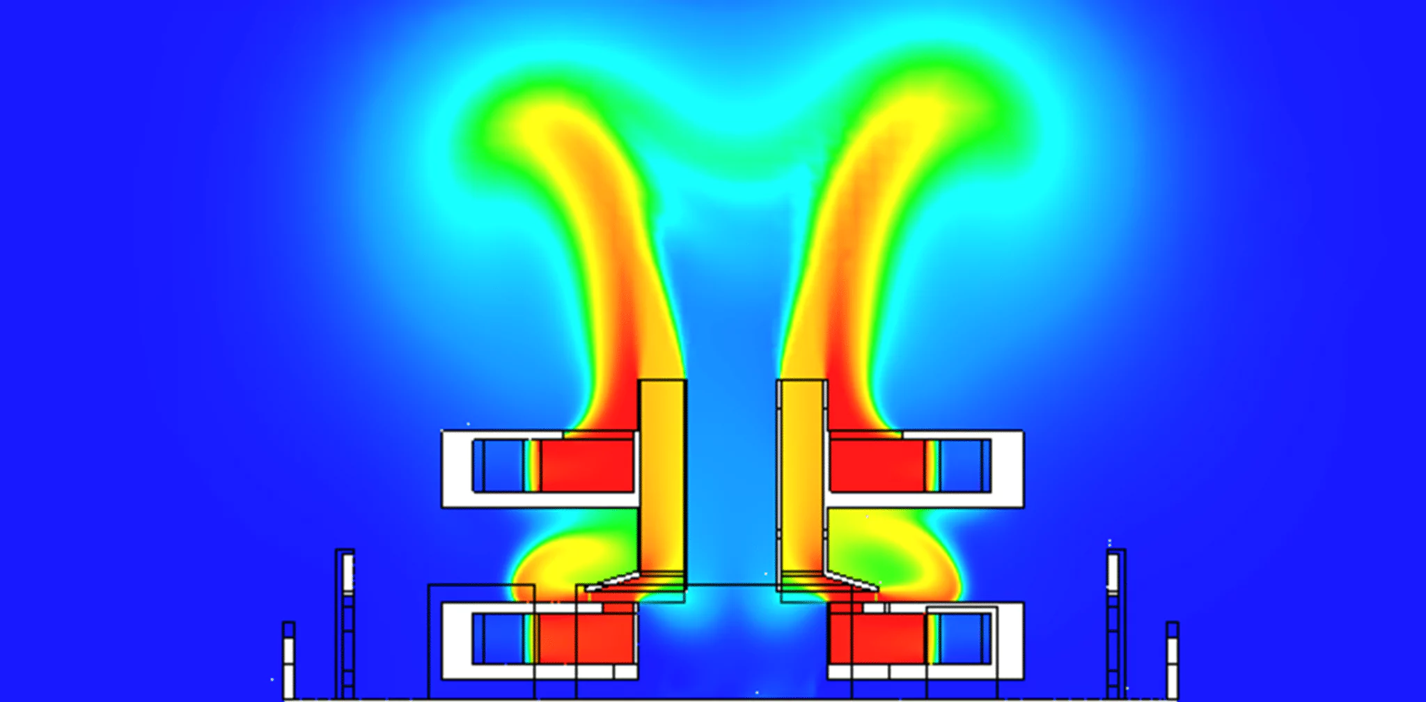
The technical expertise focused on developing a perfectly sealed connection between the compressors and the extraction ducts. This configuration is essential to channel the air expelled at 65 °C and turn the residual pressure of the machines into an ejection velocity capable of breaking through the structural wake zones. However, switching to a sealed system requires controlling the pressure losses generated by the complex geometry and the bends of the ducts, which act as resistances to the flow. The stakes are then critical: if these pressure losses exceed the static pressure available at the outlet, the air flow collapses, causing an internal overheating of the equipment.
Through CFD simulation, EOLIOS validated a design reducing the leaks from 30 % to just 3 %, ensuring that all the pneumatic energy is directed towards the extraction to compensate for the network resistances. This performance gain ensures that the fresh air remains predominant around the installations, turning a high-risk configuration into a safe, thermally controlled working environment.
“Pressure loss” refers to the loss of pressure a fluid suffers as it travels through a network: friction along the walls, bends, contractions, junctions. The more tortuous the network, the higher the resistance; if it exceeds the available pressure, the flow drops and the heat extraction is no longer ensured.
This study illustrates the importance of the contribution of numerical modelling at the design or refurbishment stage. By revealing the thermal risks well before the actual installation, we enabled the client to adjust the design to guarantee maximum efficiency in the harshest conditions.
Are you working on a project where the management of heat flows and operator comfort is decisive? Call on our CFD expertise to secure your choices and optimise your interventions from the study phase.
Expertise: the CFD study of generatorsHot-air recirculation, cooling at sea and the contribution of CFD simulation.
The compact arrangement of the units and the architectural obstacles of the vessel create wake zones where the air stagnates. The air rejected at close to 65 °C is then either immediately drawn back in by the neighbouring air intakes (short loop) or heats the general ambient air before intake (indirect recirculation), degrading the performance of the whole system.
No. Even with a sustained head wind of 6 m/s, the naval architecture generates zones of stagnation and aerodynamic separation that limit the air renewal around the installations. Without directed ventilation, these zones become thermal traps where heat accumulates, regardless of the strength of the outside wind.
A conventional calculation reasons in global balances and does not see local phenomena: recirculations, wakes, heat bubbles. CFD solves the velocity and temperature field at every point of the domain and reveals these invisible mechanisms, making it possible to test design variants before any real installation.
By developing a perfectly sealed connection between the compressors and the extraction ducts, validated by simulation. The residual pressure of the machines is converted into an ejection velocity capable of breaking through the wake zones, while controlling the network pressure losses so the flow does not collapse.
Yes. The same methodology (digital twin, real weather conditions, recirculation analysis) applies to generators, engine rooms, offshore platforms and any process rejecting heat in a confined or semi-open space.
Explore our expertise, projects and technical papers to go further than the FAQ.
This thermo-airflow study concerns the analysis of the airflows and heat rejection of 18 diesel compressors installed on the deck of an offshore vessel in the Baltic Sea. Through a high-fidelity 3D model and advanced CFD simulations, the engineers identified critical phenomena of hot-air recirculation and thermal stagnation capable of producing temperatures dangerous for the equipment and the technicians. The study made it possible to design an optimised solution for confining and extracting the flows, sharply reducing the hot-air leaks and improving the reliability of the installations, the thermal comfort of the operators and the overall safety of the system in severe climatic conditions.
Beyond the maritime case, the approach transfers to any installation rejecting heat in a constrained space: generators, engine rooms, technical rooftops, industrial platforms. To go further:
The simplest thing is to talk it through together. Our engineers reply with an initial technical read.