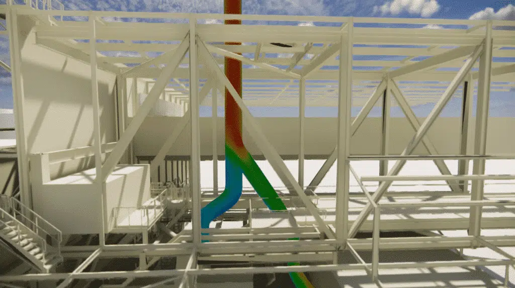
Sizing the flue-gas chimney as part of the modernisation of the aluminium melting furnaces, to control emissions and meet environmental standards.
The essentials. As part of the expansion of Aluminium Dunkerque — the installation of a new furnace no. 8 with a 65-tonne capacity — EOLIOS sized, through CFD simulation, the chimney that extracts the flue gases. The study combines the regulatory framework (Order of 2 February 1998, NF EN 13084-1), an on-site audit (thermography, smoke tests) and simulations of the melting and holding modes of furnaces 7 and 8, to ensure sufficient draft, control pressure losses and meet environmental emission standards.
The sizing of industrial chimneys in sectors handling raw materials, such as aluminium, is essential to optimise plant performance. It accounts for technical, regulatory and environmental criteria, to meet the requirements of energy efficiency and emissions reduction.
Taking a project carried out by EOLIOS as an example, this article examines the design specifics required for aluminium-furnace chimneys, underlining the importance of advanced solutions to control flue-gas and fume emissions while meeting environmental standards.
Extracting combustion fumes is crucial for the environment, safety and operator comfort. The sizing of the chimney is governed by regulations. The chimney acts as a fume extractor by creating a suction to draw the fumes out of the combustion chamber. It releases the fumes high up to promote their dispersion and reduce their environmental impact.
There is no legal obligation, but a standard recommends an inspection every two years. Chimneys are exposed to high temperatures and acid attack, requiring regular monitoring.
The main regulations are the French Environmental Code and the Order of 2 February 1998. Standards such as NF EN 13084-1, EN 1990, EN ISO 14122-1 and combustion data sheets provide guidance on sizing, safety, compliance and the management of environmental impacts linked to combustion-fume extraction.
Safety, environment & compliance. Combustion fumes are hot, corrosive and can contain harmful compounds (aluminium particles, toxic gases). Undersizing compromises the extraction suction, the dispersion of emissions and compliance with the Order of 2 February 1998.
As part of the project to increase ingot-production capacity, the installation of a new furnace (no. 8) alongside the existing furnace (no. 7) is planned. This furnace will have a capacity of 65 tonnes and will be used to melt solid metals, as well as to keep the metal liquid ready for casting in the ingot-production line. The two furnaces work in tandem to ensure production continuity. This extension will require additional flue-gas extraction to the existing chimney.
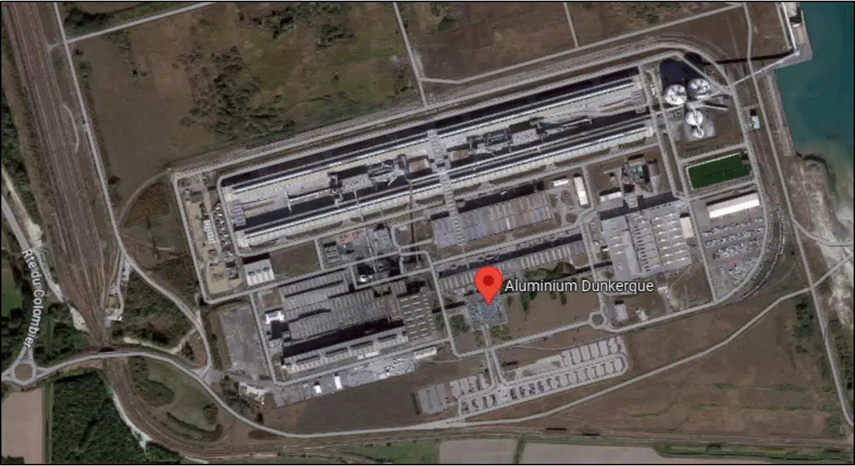
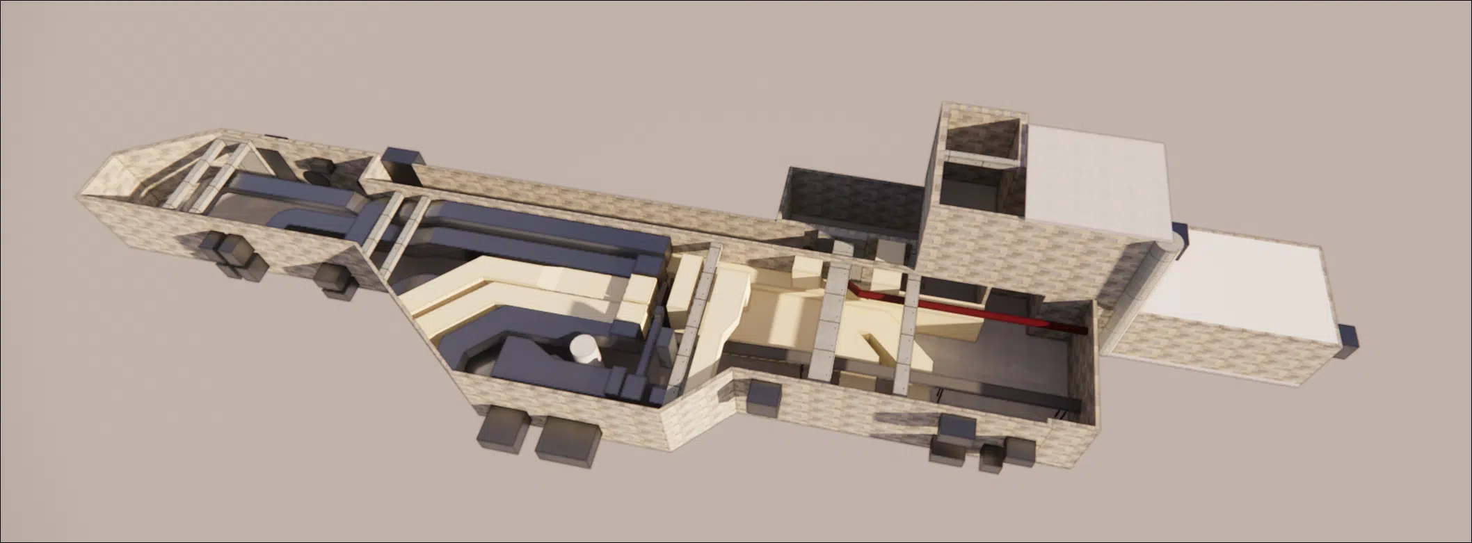
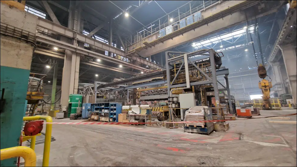
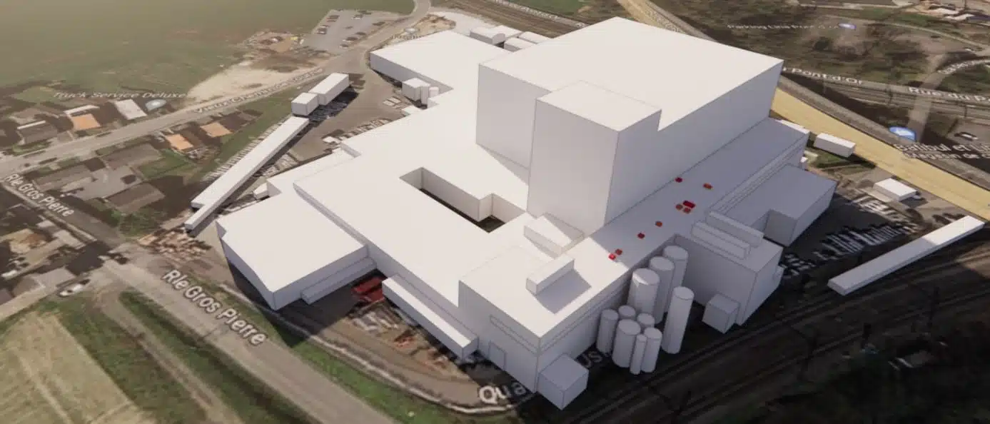
The Aluminium Dunkerque site, built in 1991, initially comprised 6 aluminium furnaces, 3 slab-casting units and 1 ingot-production line. In 2004, a seventh furnace was installed, and in 2015 a second ingot-production line was added. In 2022, the first ingot-production line was dismantled. The foundry hall houses the furnaces aligned lengthwise, with roof ventilators for air extraction and louvres for fresh-air intake.
Sizing an industrial chimney for aluminium melting furnaces depends on several factors, in particular:
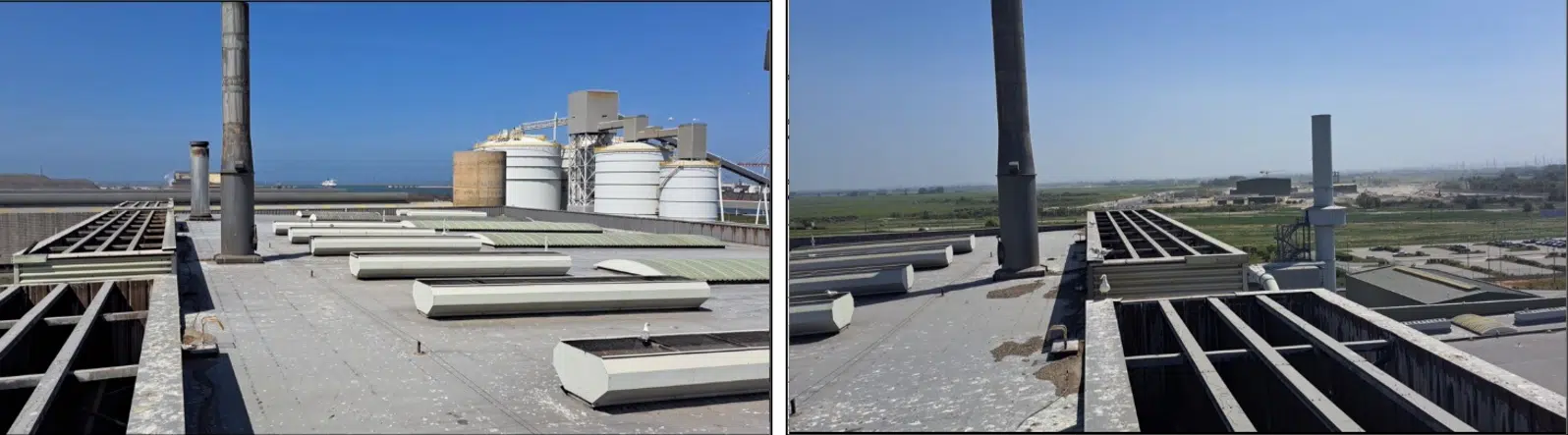
The chimney height is determined according to the levels of pollutant emissions and the presence of obstacles that could hinder gas dispersion. It cannot be less than 10 metres. This is set in accordance with articles 53 to 56 of the Order of 2 February 1998, or calculated from the results of a site-specific gas-dispersion study.
CFD is used to simulate and analyse the behaviour of fluids (air, water, gas…) inside a furnace, in order to understand the phenomena of heat transfer, flow velocity and mixing. Thermography, for its part, visualises temperature variations using infrared cameras, which convert temperature differences into thermal images. These images provide valuable information on the hot and cold zones and the temperature gradients in the industrial furnace.
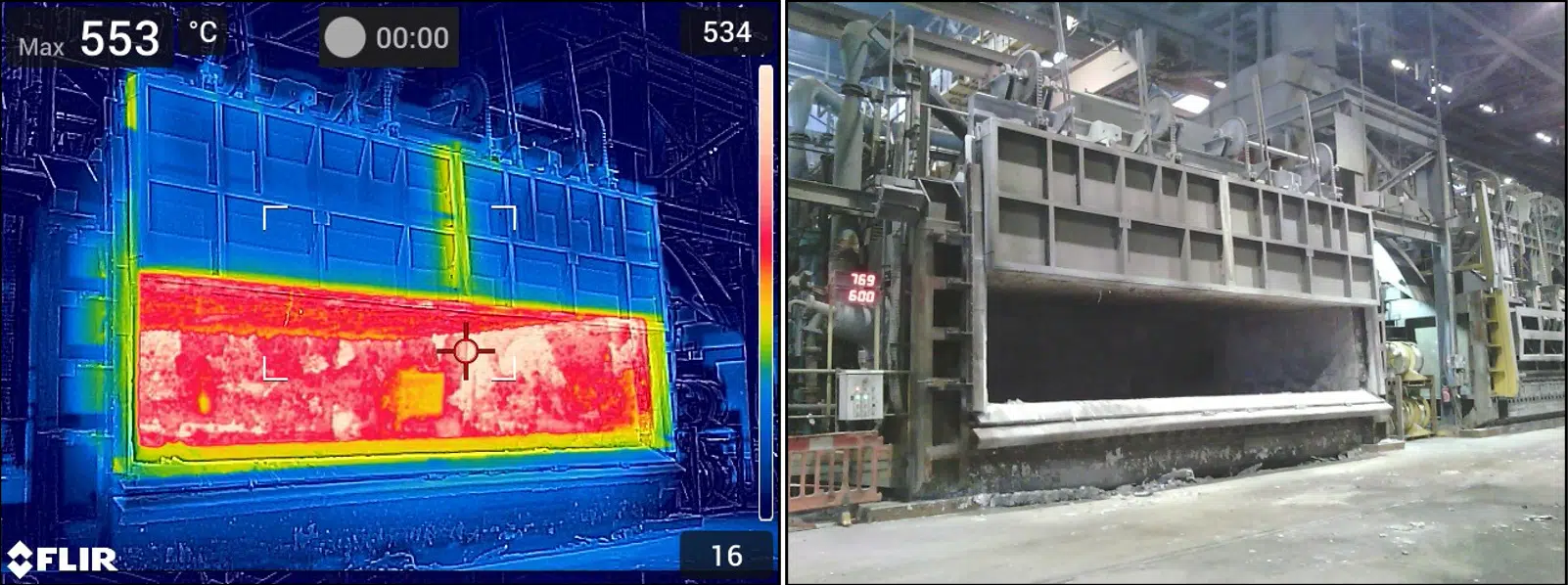
By combining thermography and CFD, the engineers can take corrective measures to improve the furnace's energy efficiency, optimise the production processes, reduce operating costs and maximise overall performance. Thermography provides real-time, non-invasive data on the temperatures inside the furnace, which makes it easier to detect potential problems (excessive hot spots, zones of insufficient cooling).
The thermal audit aims to identify the locations where heat is concentrated and to create a map of the hot and cold zones. It is important to note that the temperatures given are intended to provide a general estimate rather than a precise measurement.
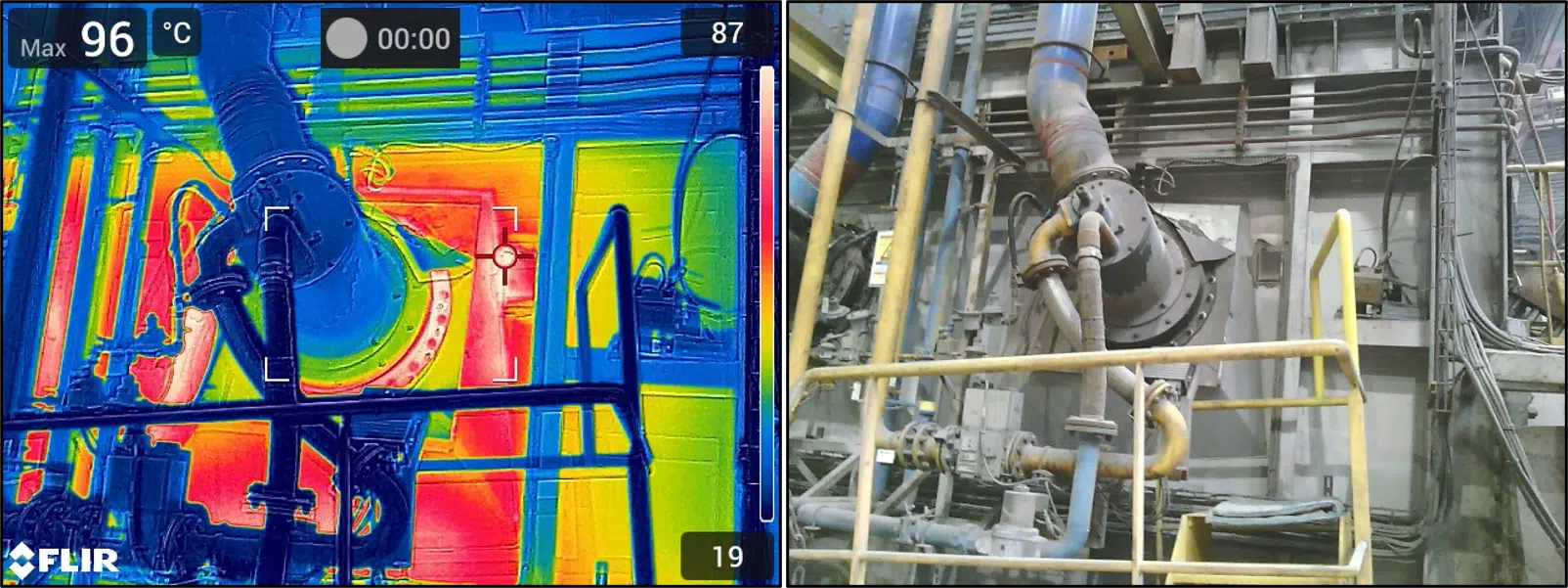
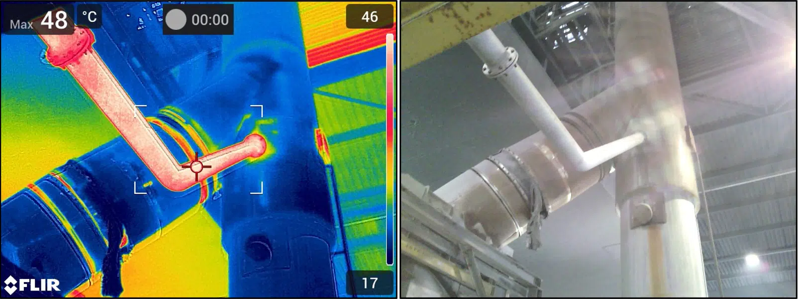
The smoke tests aim to visualise the ventilation around furnace 7. Like the thermal images, these tests provide complementary data for validating the simulations. Given the presence of openings such as the air supply and the furnace's side openings, it is essential to consider the volume surrounding the furnace and the airflow conditions that prevail there.
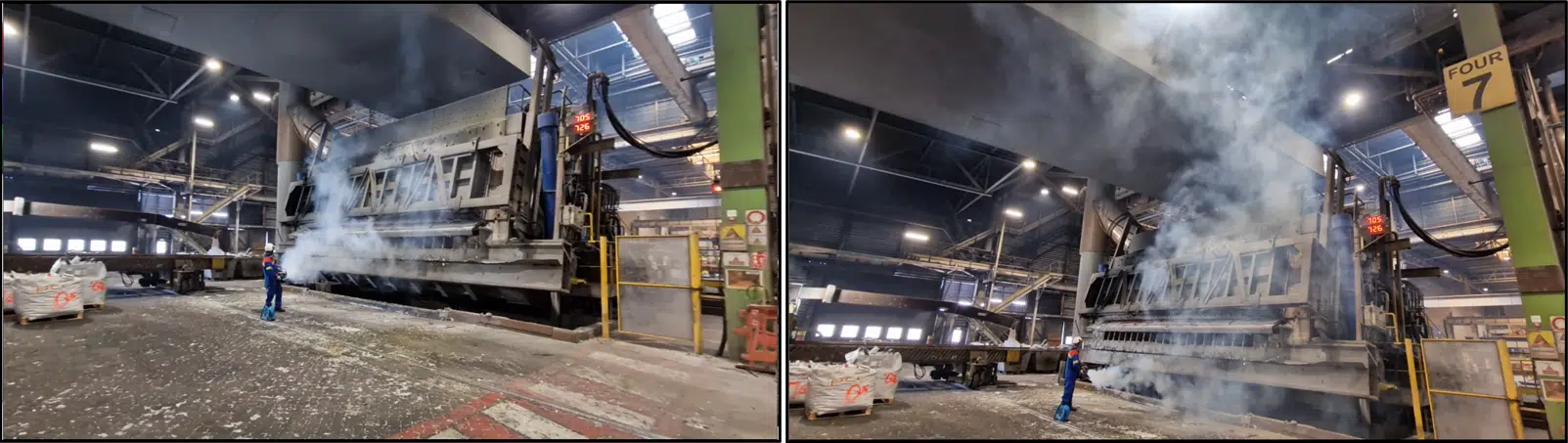
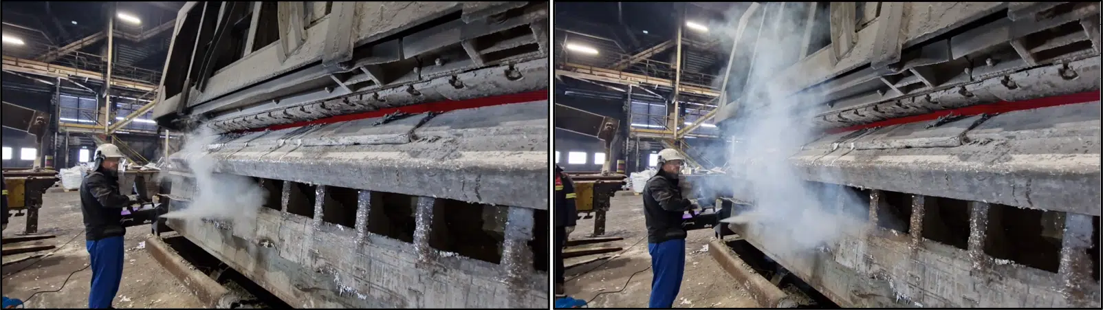
The furnace operates in several distinct phases: melting, holding, temperature rise, door opening and other operations. The gas flow varies across these phases and is influenced by the number of furnaces in operation. Adding furnace 8 in alternation is considered in order to reach the gas flow rates required by the regulations.
One of the essential methods in our approach is CFD simulation (Computational Fluid Dynamics). This advanced technique makes it possible to analyse and model the behaviour of fluids (gases, liquids, suspensions) using complex mathematical equations solved by computer. We thus provide precise, detailed predictions of aerothermal phenomena, fluid flows, heat transfer and pressure losses.
In the case of chimney sizing for an industrial furnace, CFD is particularly useful for understanding and optimising the combustion process. By studying the fluid properties (temperature, velocity, pressure) and their interaction with the various components of the chimney, we assess the pressure losses — that is, the pressures lost as the flow passes through the system.
Pressure loss is the drop in pressure experienced by a fluid flowing through a duct, caused by friction and singularities (bends, changes of section). On a chimney, excessive pressure losses reduce the draft and compromise fume extraction.
In addition, CFD makes it possible to analyse the pressure rise from natural thermal draft in the chimney — essential to ensure efficient fume extraction using the temperature difference between inside and outside. We can thus optimise the design for maximum draft while minimising pressure losses. Finally, we study erosion by the dust in the fumes: CFD predicts the zones sensitive to erosion, identifies the wear mechanisms and proposes suitable protective solutions (resistant coatings, geometry changes).
Thermal draft is the upward movement of hot gases in the chimney, driven by their density difference with the colder outside air. The greater the temperature difference and the height, the stronger the draft : it is the natural engine of fume extraction.
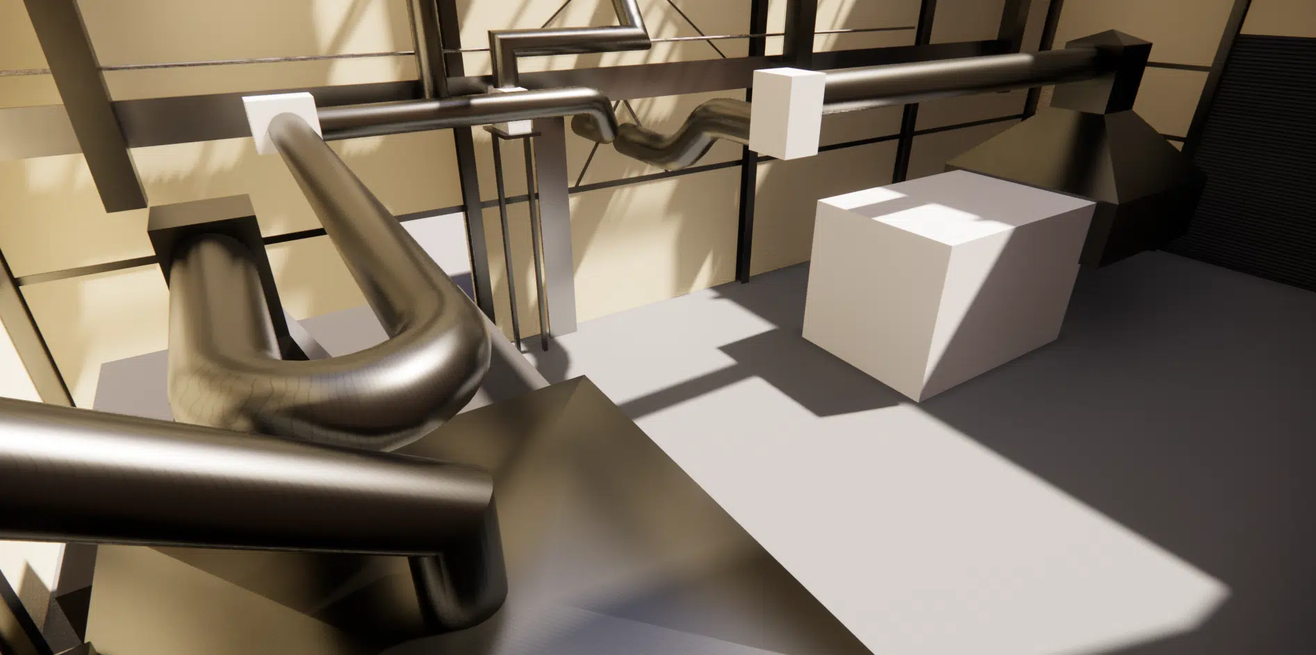
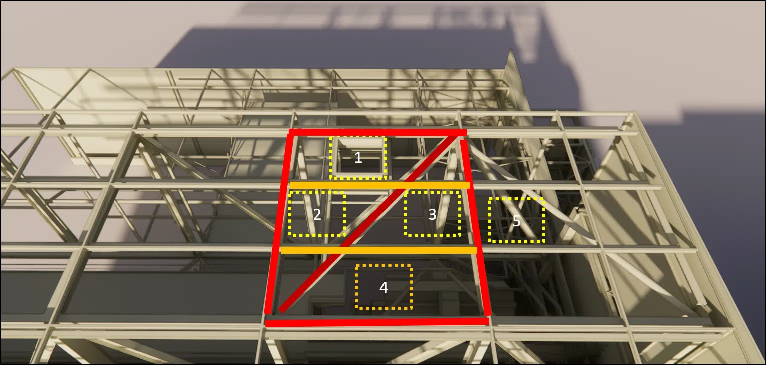
The roof structure must be locally reinforced to allow the chimney to pass through. A specific reinforcement is planned, in the form of a diagonal beam, to facilitate this passage. Given the space constraints on the roof, there are five possible options for the location of this passage. Positions 1 and 5 are preferred for their accessibility and suitability.
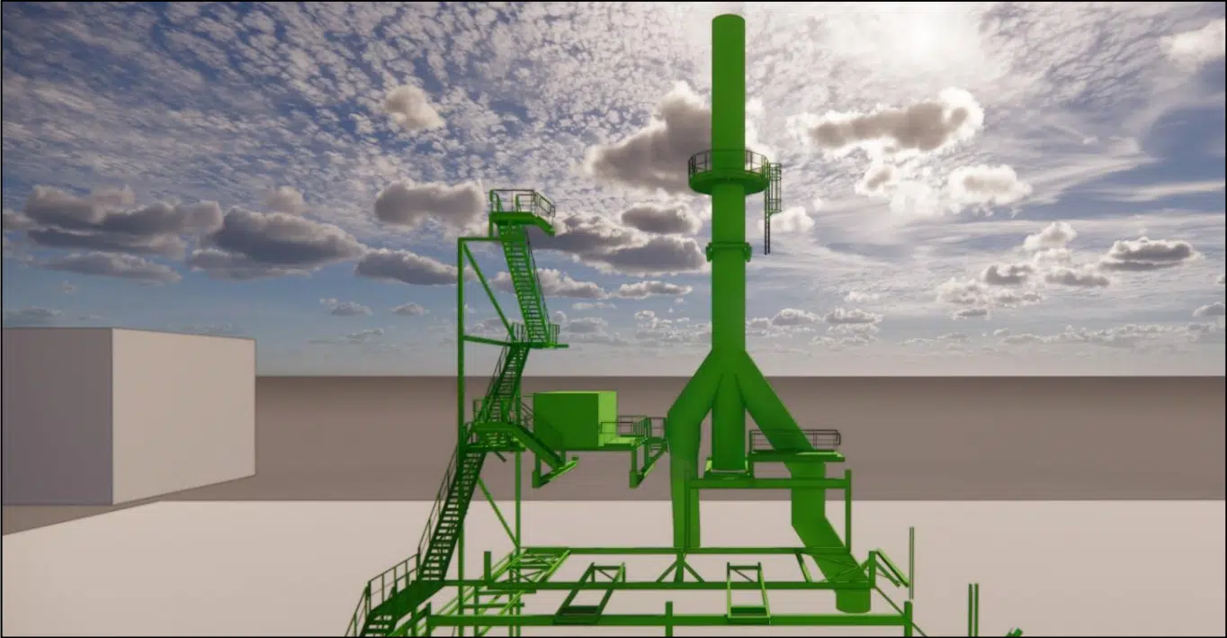
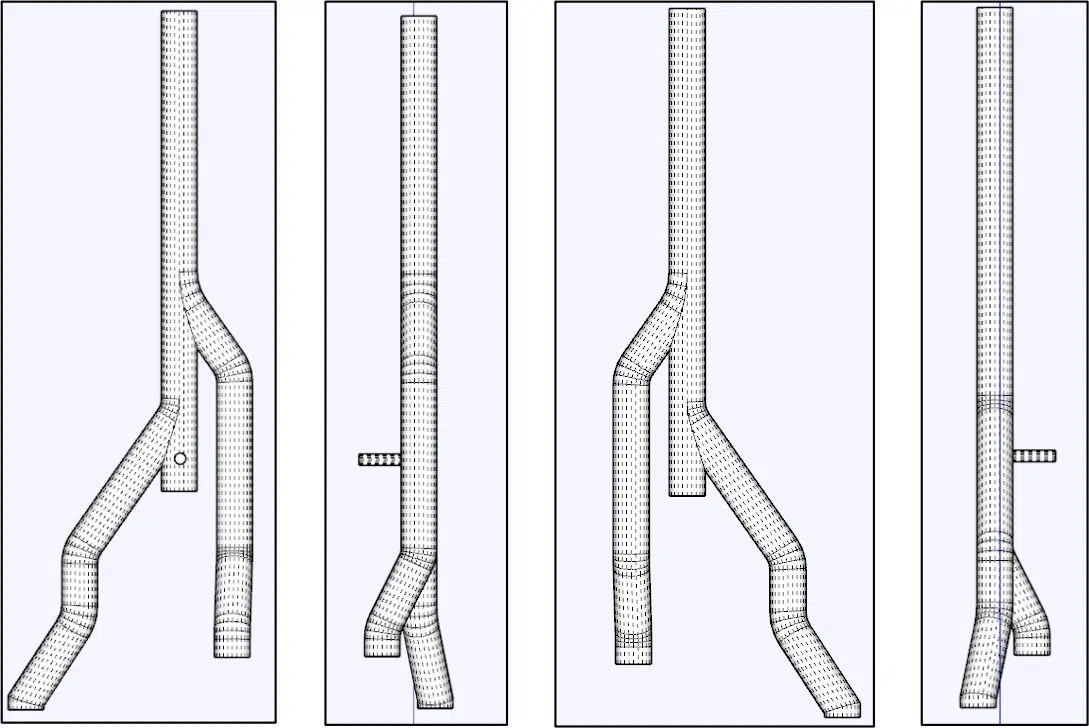
We optimised the bends and connections to improve the flow efficiency. Our approach is to limit each bend to a maximum of 3 elements to control the implementation costs.
We ran simulations for the two most demanding scenarios: the melting mode of furnaces 7 and 8, and the holding mode of furnaces 7 and 8. The main objective was to assess the ejection velocities and air flow rates at the air intakes located above the measurement point.
![Velocity plot on the axis and outlet section — [7M8M]](https://eolios.fr/wp-content/uploads/2023/10/Capture9.png.webp)
![Velocity plot on the axis and outlet section — [7F8F]](https://eolios.fr/wp-content/uploads/2023/10/Capture10.png.webp)
The dimensions of the air intakes were similar to those of the chimneys of furnaces 1 to 6. For the first chimney, the simulations showed that the air intakes had a limited impact on the flow, with inlet rates well below the set target; nevertheless, the outlet velocities remained within the objectives. For the second chimney, the pressure losses caused by the sharp bends in the furnace 8 duct had a negative impact on the draft, reducing the outside-air supply and, in the case of melting furnaces 7-8, reversing the flow direction. However, the difference in temperature distribution between the two chimneys remained minimal.
Expertise: industrial chimney sizingChimney sizing, thermal draft and CFD simulation of industrial emissions.
A properly sized chimney creates the suction needed to draw fumes out of the combustion chamber, then releases them high enough to promote dispersion and limit environmental impact. Sizing ensures sufficient draft, controls pressure losses and secures regulatory compliance.
It depends on pollutant-emission levels and obstacles likely to hinder gas dispersion. It cannot be less than 10 metres and is calculated according to articles 53 to 56 of the Order of 2 February 1998, or from a site-specific dispersion study.
Thermal draft is the upward movement of hot gases, driven by their density difference with the colder outside air. It is the natural engine of fume extraction : CFD helps optimise the design to maximise this draft while minimising pressure losses. More detail in our paper on the thermal draft effect.
Thermography and smoke tests provide real measurements (hot zones, ventilation around the furnace) used to calibrate and validate the simulations. Combined with CFD, they make it possible to analyse scenarios impossible to reproduce on site and to make sizing more reliable.
The main references are the French Environmental Code and the Order of 2 February 1998, complemented by standards such as NF EN 13084-1, EN 1990 and EN ISO 14122-1. They govern sizing, safety, compliance and the management of environmental impacts.
Explore our expertise, projects and technical papers to go further than the FAQ.
CFD sizing of the flue-gas chimney for the modernisation of the aluminium melting furnaces (Aluminium Dunkerque): regulatory framework (Order of 2 February 1998, NF EN 13084-1), key factors (gas flow, temperature, fume composition), on-site audit (thermography, smoke tests), 3D model and duct optimisation, simulations of the melting/holding modes of furnaces 7 and 8 and analysis of the thermal draft.
The simplest thing is to talk it through together. Our engineers reply with an initial technical read.