Assessment of the pressure losses in the air-diffusion plenum beneath the CNIT in Paris, to ensure it works correctly when smoke control is needed.
The aim of this project is to assess the pressure losses in the air-diffusion plenum beneath the CNIT in Paris, to ensure it works correctly when smoke control is needed. A 3D model of the plenum was built to assess the pressures and problem zones.
The essentials. Beneath the CNIT in Paris, the plenum that feeds the smoke control is cluttered with ducts that reduce the air passage cross-section. EOLIOS built a detailed 3D model, located in CFD the zones of high pressure loss in the worst-case scenario, then proposed optimisations (duct repositioning, deflectors, cowlings) that halve the pressure loss.
The aim of this project is to assess the pressure distribution within the air-diffusion plenum beneath the CNIT in Paris, in order to ensure the pressure losses do not exceed the limits of the systems and thus guarantee correct operation when smoke control is needed. This assessment is carried out in a context where the plenum is cluttered, with a large number of ducts that reduce the air passage cross-section.
Once the pressure losses have been assessed in a standard scenario, the aim is to propose optimisations to reduce the pressure losses caused by the ducts.
Pressure loss is the drop in pressure the air undergoes as it flows: every bend, contraction or obstacle dissipates a share of it. Too high, it prevents the fan from reaching the required flow rate. See the paper pressure loss and hydraulic resistance.
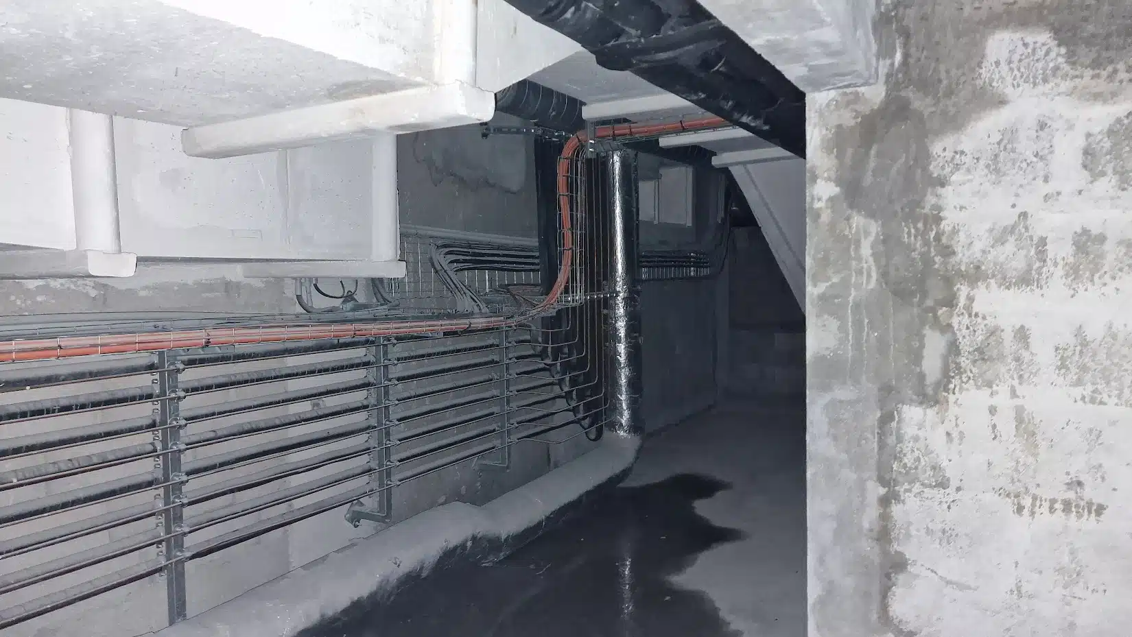
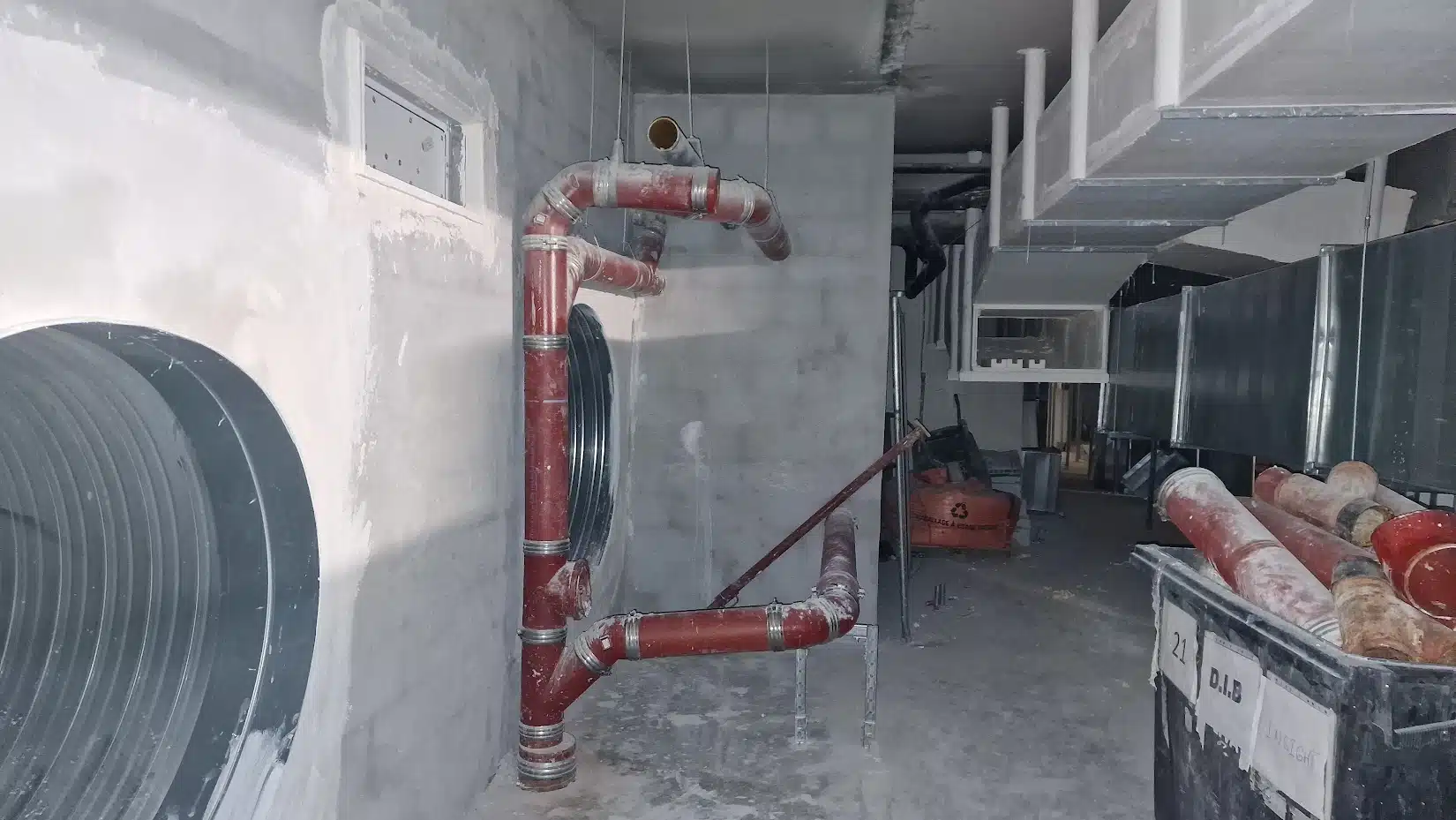
In this project, it is crucial to validate, through computational fluid dynamics (CFD) simulations, the pressure loss induced by the position of the ducts, and possibly to consider installing deflectors.
A plenum is a large buffer volume placed upstream of the diffusion points, which equalises the pressure before distributing the air. In smoke control, it must deliver a high flow rate without its internal geometry creating a prohibitive pressure loss.
The challenge is to find solutions that minimise the pressure losses and optimise the operation of the air-diffusion system to ensure maximum efficiency and safety when smoke control is needed.
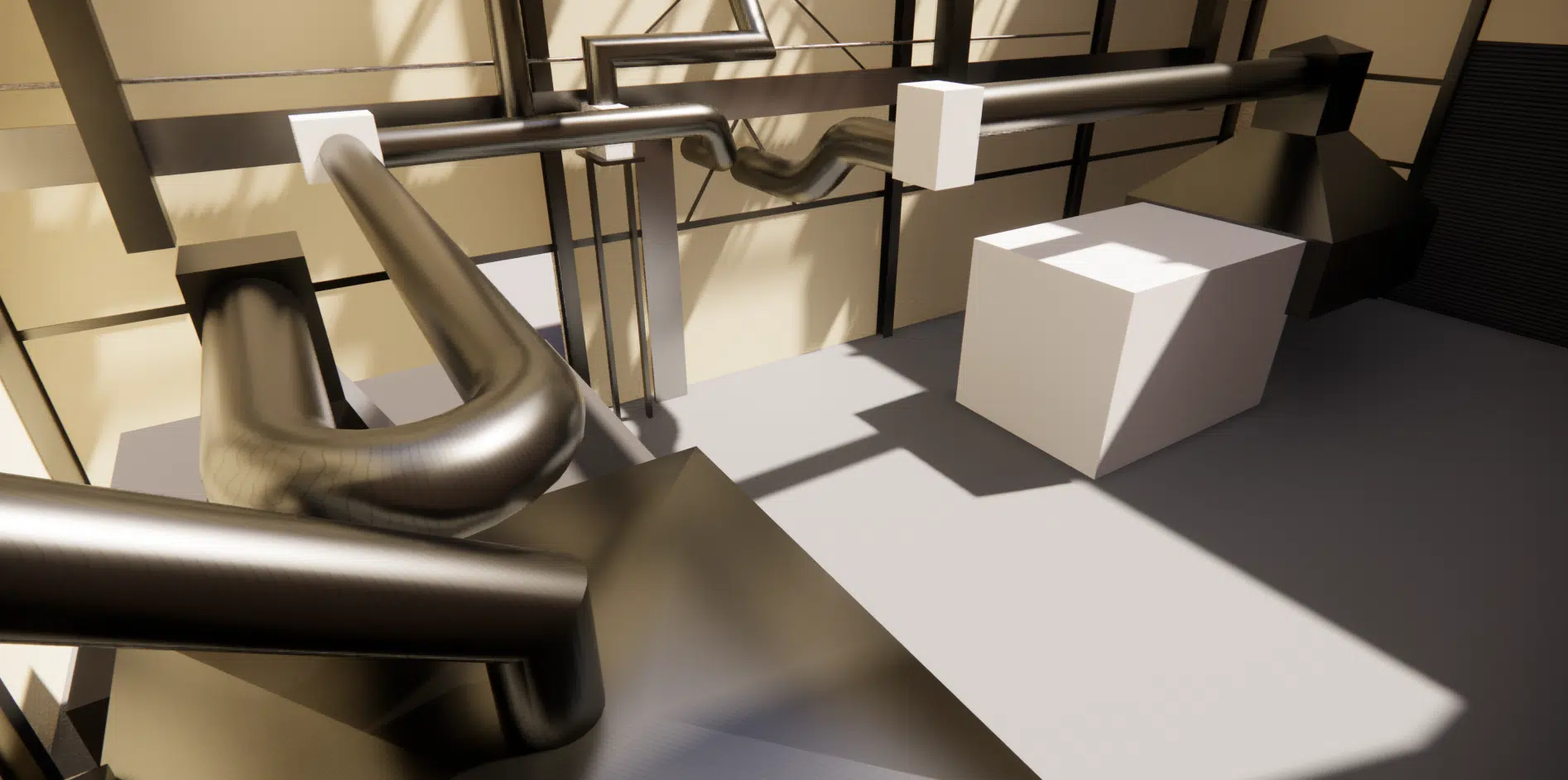
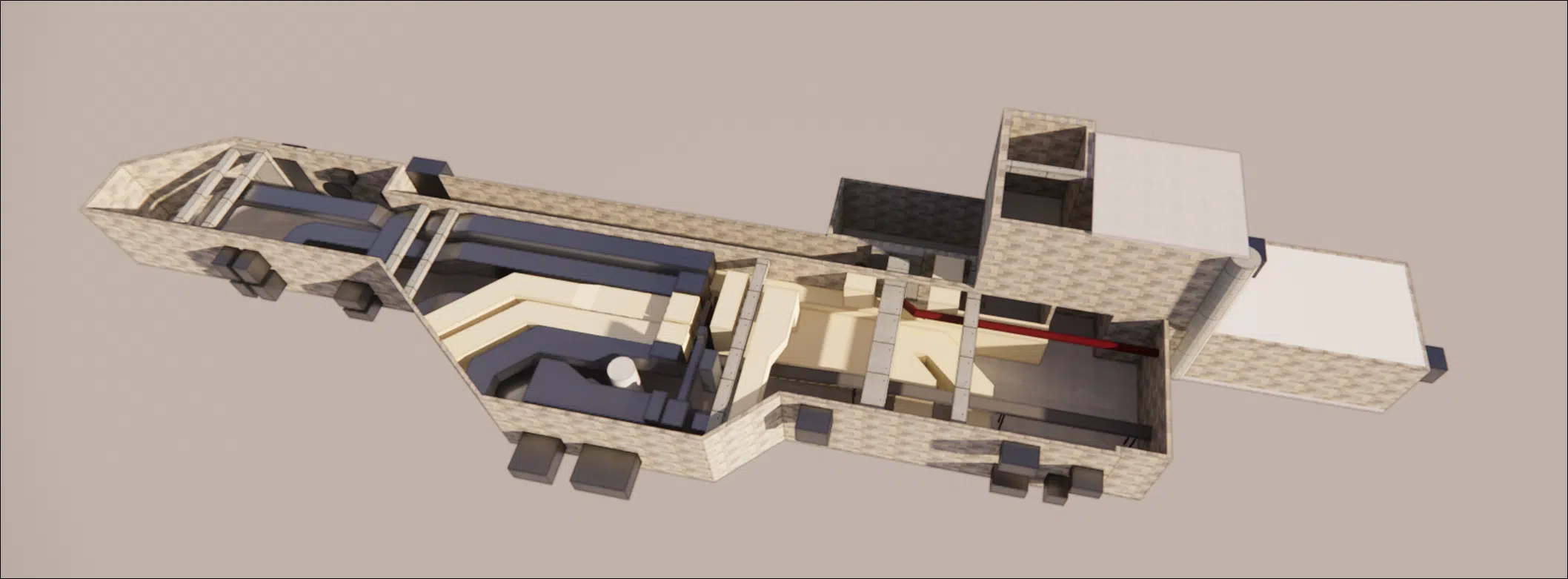
For this study, the overall volume of the plenum was modelled precisely, taking into account the layout of all the networks to come as close as possible to real operating conditions. Based on the measurements taken on site during an audit, all the openings, beams, ducts, masonry and other geometries of the plenum were modelled accurately.
The masonry at the plenum inlet was also taken into account, making it possible to accurately assess the impact of these elements on the fresh-air supply. Thus, all the main airflow obstructions were remodelled to be incorporated into the studies.
To assess the maximum pressure loss within the plenum and verify the sizing of the installations, the worst-case scenario must be used. To do this, it is essential to consider the case where the maximum amount of air is drawn from the plenum.
By taking this extreme scenario into account, it is possible to ensure that the installations are adequately sized to cope with the most demanding conditions.
Computational fluid dynamics (CFD) brings together all the numerical methods used to study the flow of a fluid in a given environment. These flows are governed by partial differential equations that cannot be solved analytically. The finite-element method makes it possible to solve these equations numerically, yielding an approximate solution to a physical problem.
When applied to buildings, a CFD study can give the designer valuable information on the likely air velocities, pressures and temperatures inside and around the built spaces.
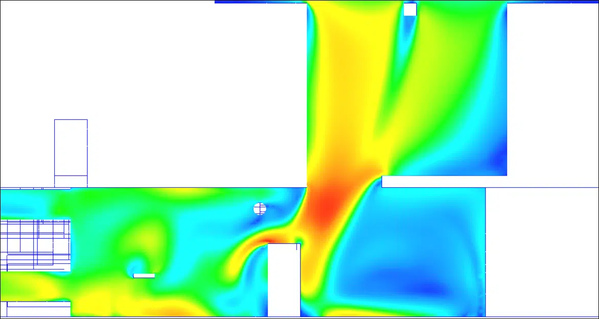
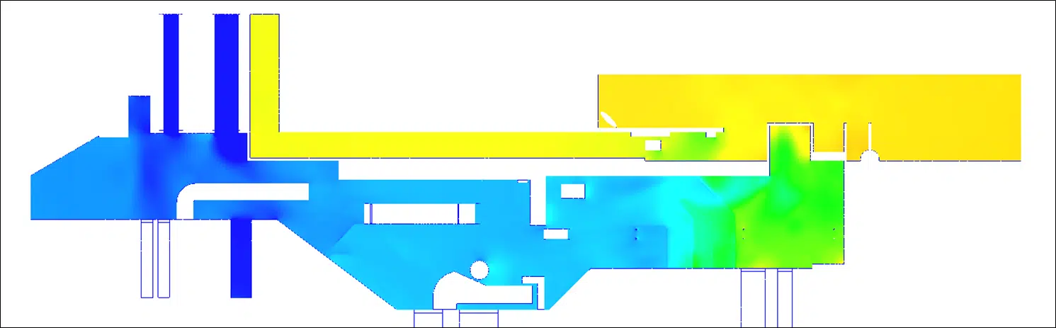
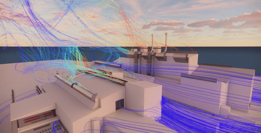
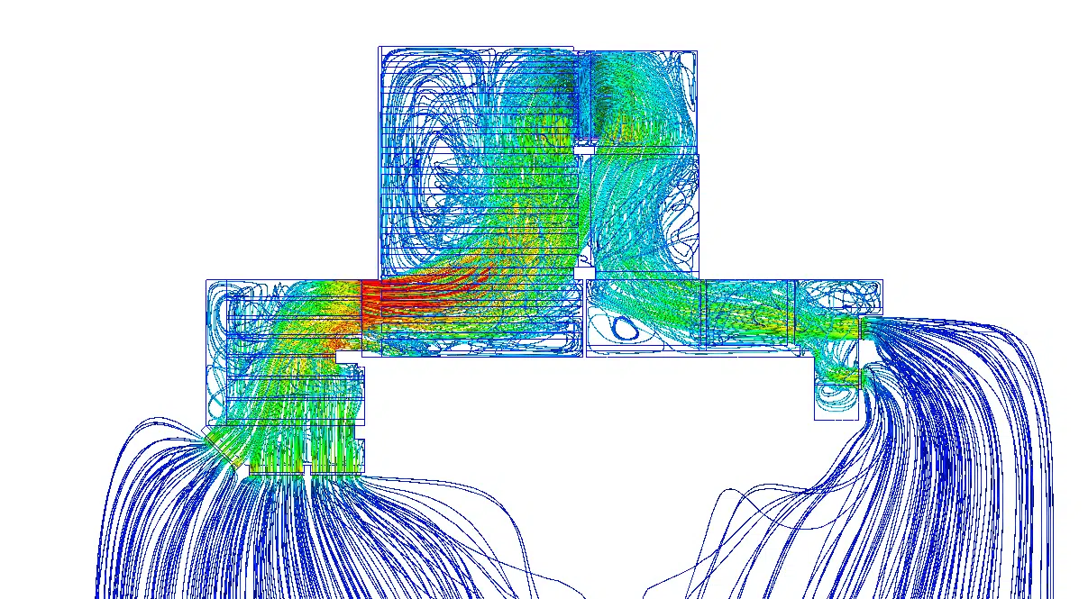
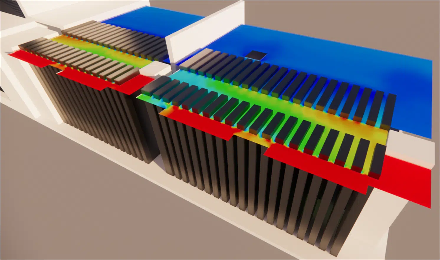
A CFD study is therefore carried out on the plenum model that faithfully reproduces reality, making it possible to identify the zones of high pressure loss under the current conditions that must be modified to reach the pressure-loss targets required for the smoke-control system to work properly.
Many technical solutions were proposed to smooth the air circulation in the plenum and optimise smoke extraction, such as changes to the position of the ducts, a rearrangement of the problematic masonry, an aerodynamic optimisation of the volumes present, or the installation of cowlings to better guide the airflow towards the outlet. These optimisations relate to our smoke-extraction engineering.
A deflector is a profiled part added into the flow to redirect the air smoothly and steer it clear of an obstacle or a sharp angle. Well placed, it removes separation zones and lowers the local pressure loss.
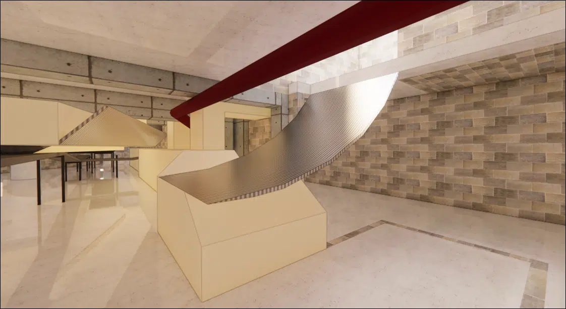
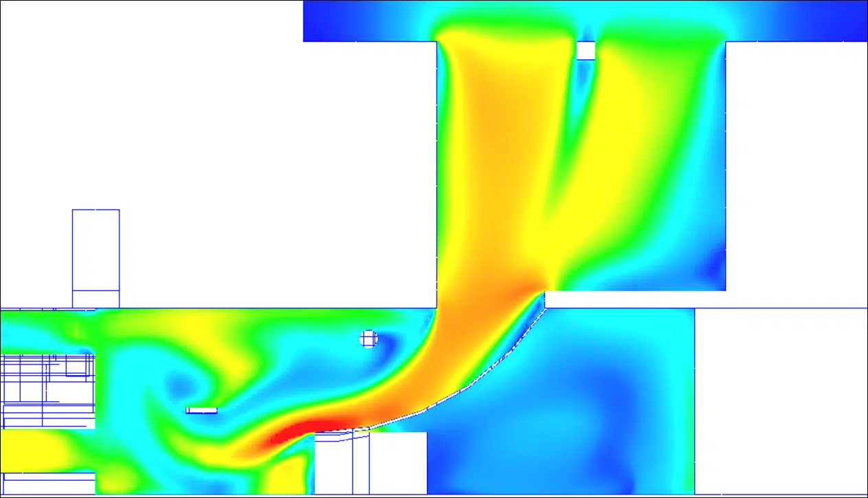
The various optimisations carried out made it possible to considerably reduce the pressure loss compared with the baseline design. The final scenario studied, which incorporates all the improvements possible within the project constraints, shows a pressure loss halved compared with the current situation.
Moreover, for the worst case, the pressure at the end of the plenum is around the target set for the general case, which was far from the case in the initial configuration.
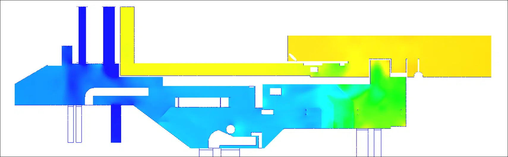
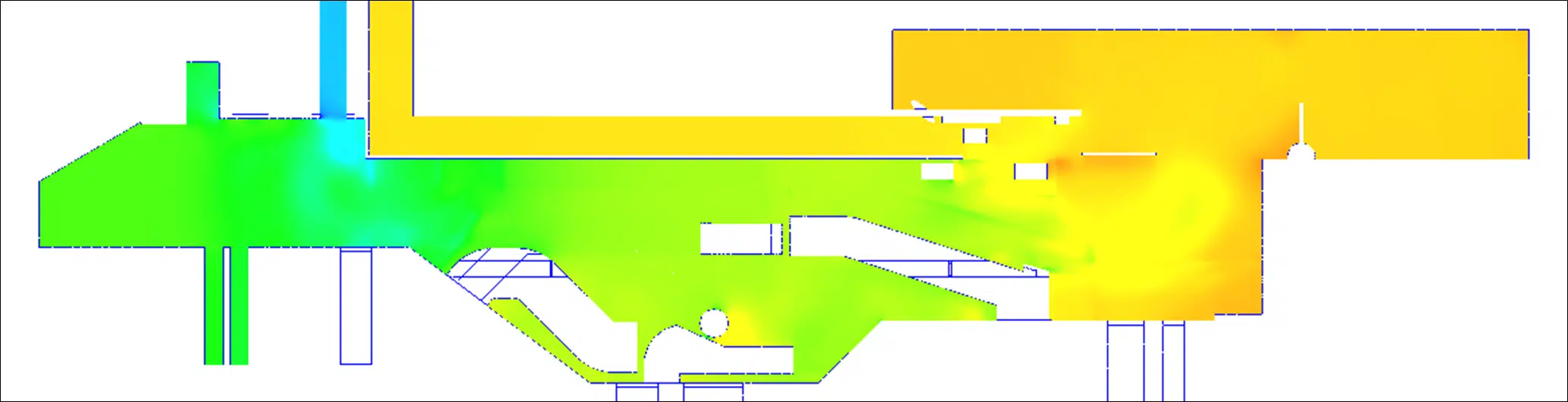
The studies carried out aimed to verify the design of the systems against a smoke-control scenario. This means the focus was on assessing the performance of the installations under conditions where a rapid evacuation of smoke and heat is needed in the event of fire. This makes it possible to ensure that the systems meet the regulatory fire-safety requirements and that they can protect the building's occupants in an emergency.
Key takeaway. On an already-built plenum, you gain aerodynamics rather than space: repositioning a few ducts and guiding the flow is enough to halve the pressure loss and bring the end-of-plenum pressure back to target, without major works.
Diffusion plenum, pressure losses and the smoke-control challenge beneath the CNIT.
It is a large volume beneath the building that distributes air towards the diffusion points. In smoke control, it must pass a high flow rate with a controlled pressure loss to evacuate smoke and heat quickly. A similar challenge was addressed on our project smoke-extraction plenum AF1.
Ducts, beams and masonry reduce the passage cross-section and force the air around obstacles. Every change of section or direction dissipates energy, which increases the total pressure loss and the pressure the system must overcome.
By working on the geometry: repositioning some ducts, rounding or cowling the sharp edges, adding deflectors to guide the flow. These local measures were enough here to halve the pressure loss.
The sizing must hold in the worst case, the one where the flow drawn from the plenum is maximal. If the pressure stays within the fans' limits in that case, it is guaranteed for all the others.
It verifies that the smoke-control network evacuates the required flow under regulatory conditions, so that smoke and heat are extracted fast enough to protect occupants and responders.
Explore our expertise, projects and technical papers to go further than the FAQ.
The project involves assessing the pressure losses in the air-diffusion plenum beneath the CNIT in Paris, in order to guarantee its correct operation when smoke control is needed. The plenum is cluttered with a large number of ducts, which reduce the air passage cross-section. CFD simulations are run to assess the pressure losses and propose optimisations to reduce them. A precise 3D model of the plenum is built, together with CFD studies to identify the zones of high pressure loss. Various technical solutions are proposed (changing the position of the ducts, installing cowlings) to smooth the air circulation. The optimisations carried out made it possible to considerably reduce the pressure losses compared with the initial design.
The simplest thing is to talk it through together. Our engineers reply with an initial technical read.