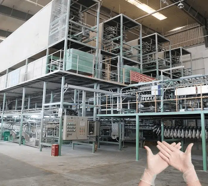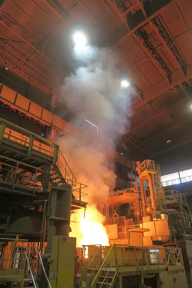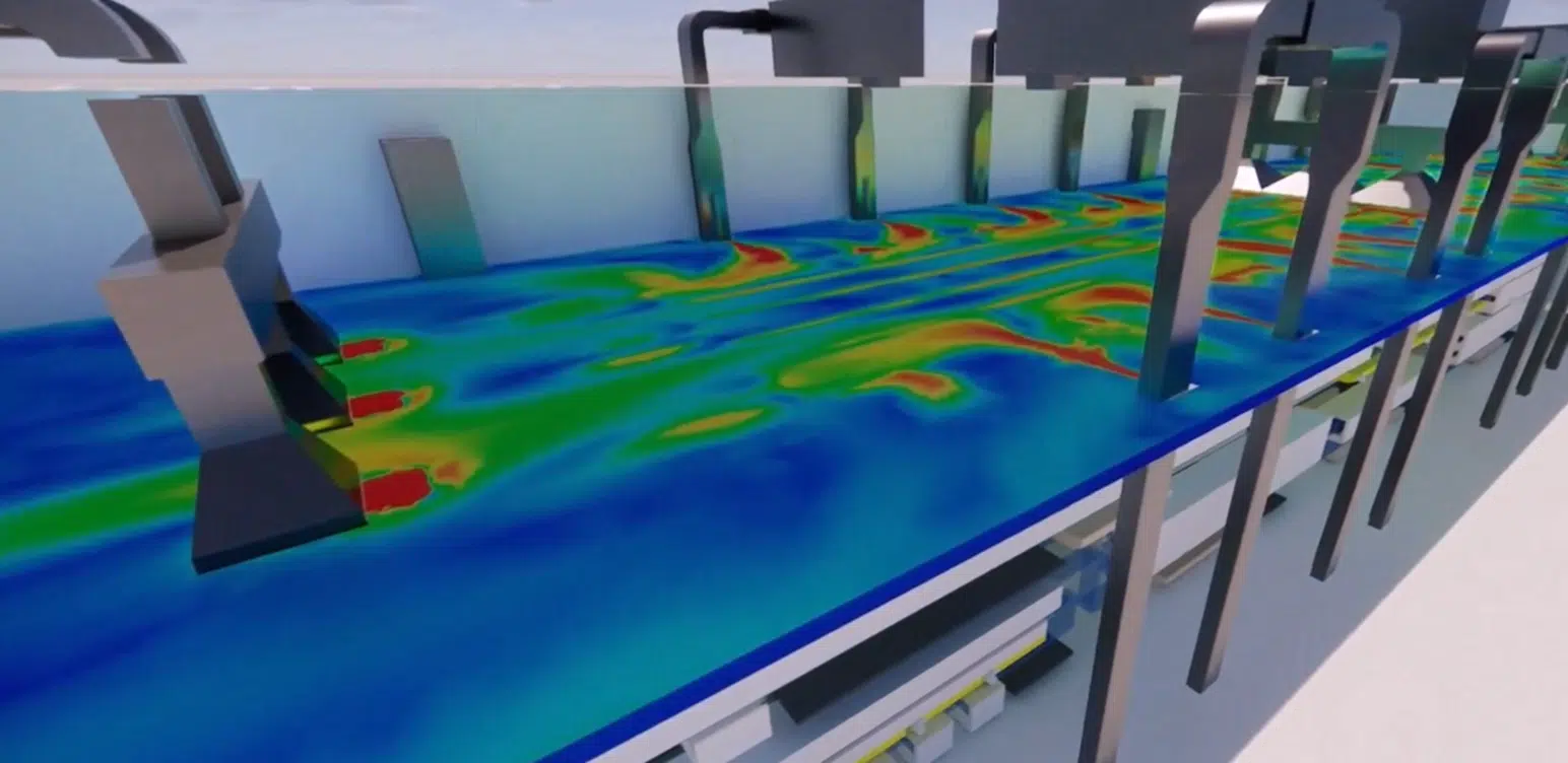
Using CFD simulation, EOLIOS verified and improved the design of the thermal-regulation system of a plant in Canada, whose innovative process combines several high-temperature furnaces.
The aim of this study is to verify and improve the design of the thermal-regulation system of a plant located in Canada using CFD numerical modelling. The goal is to understand and master the particular thermo-airflow phenomena induced by the various manufacturing stages of an innovative process combining high-temperature furnaces.
The study is built around four areas: optimising the diffusion of outdoor air, understanding the temperature distribution across the seasons, assessing operator thermal comfort and studying pollutant extraction, all focused on the production room.
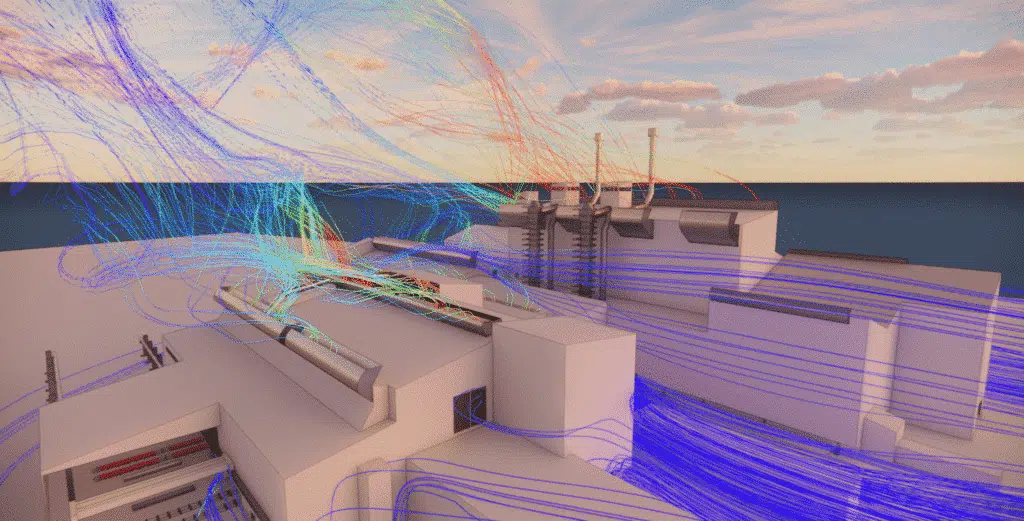
The simulations were carried out using the CFD (Computational Fluid Dynamics) method, which makes it possible to analyse and predict the movement of fluids such as air. This virtual approach makes it possible to simulate the thermo-airflow phenomena in the plant, taking into account the interactions between the various surfaces, the heat sources and the airflows. With CFD, it becomes possible to visualise and analyse the flows and temperatures in detail, for a better understanding of the processes and an optimisation of the performance and safety of the installations.
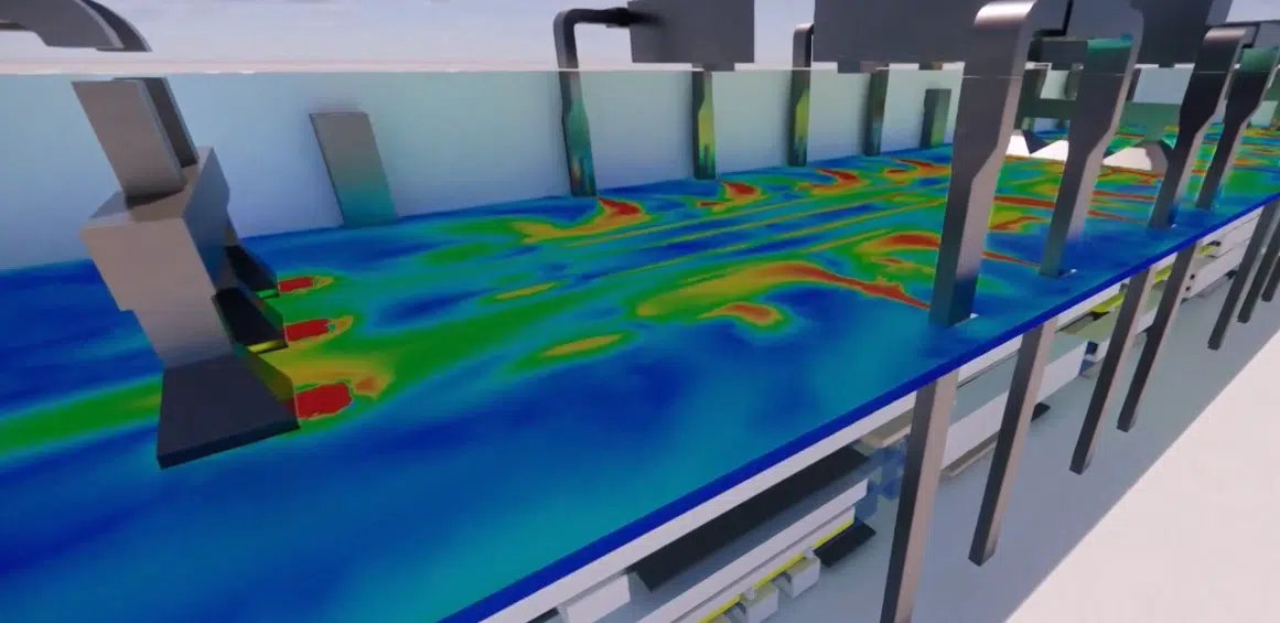
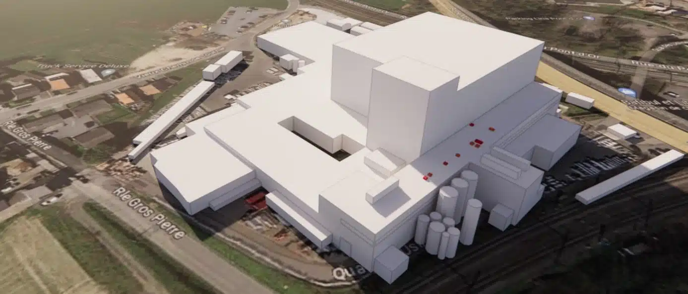
Geometric modelling is a key step: it faithfully represents the building's geometry and defines the boundary conditions (walls, openings to the outside, internal heat gains), while simplifying the model to make the results easier to interpret. For the 3D model of the plant, all the air volumes and walls in contact with the outside were reproduced, along with the surrounding rooms — in order to account for the heat transfers between rooms and the thermal bridges related to the materials.
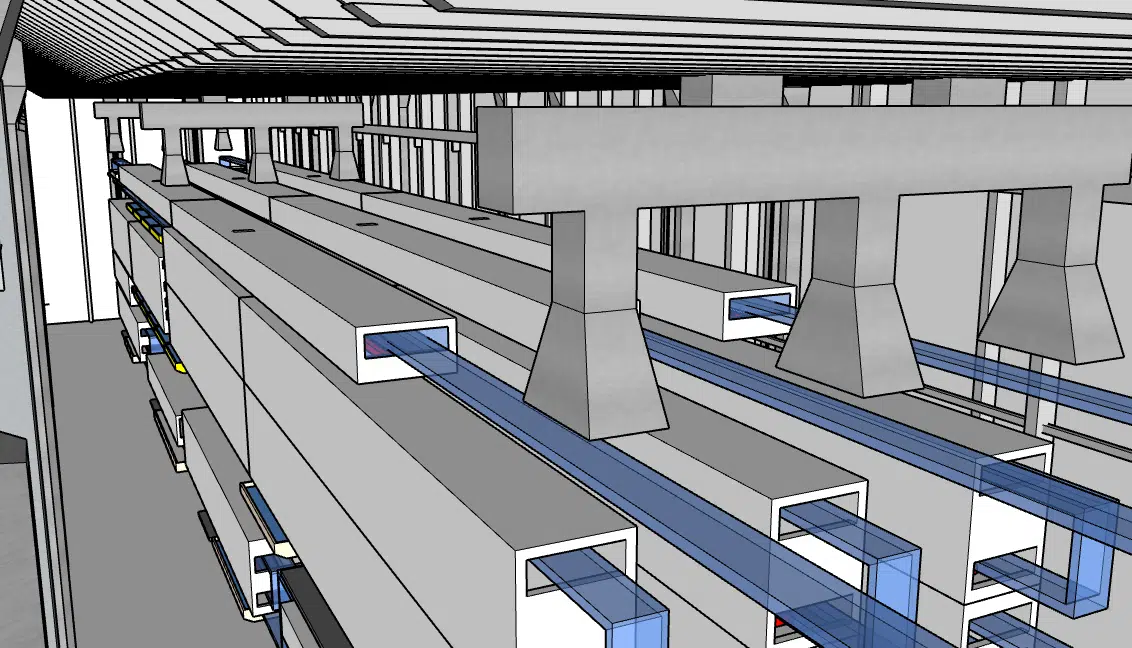
The production line and its processes were modelled — notably the furnaces — as were the air-distribution systems of the hall's air conditioning (ceiling supply and extract fans). Three high-level louvres on the west façade, ducted over the full height of the wall, let outdoor air in through the lower part. The temperatures, powers and flow rates of the machines were entered; since the ventilation system depends on the outdoor conditions (from −23 °C in winter to 32 °C in summer), the study covered both seasons.
The first simulations were run for summer operation — the most critical case because of the high temperatures — with all heat-generating systems at their maximum temperature, an outdoor temperature of 32 °C and solar gains taken into account.
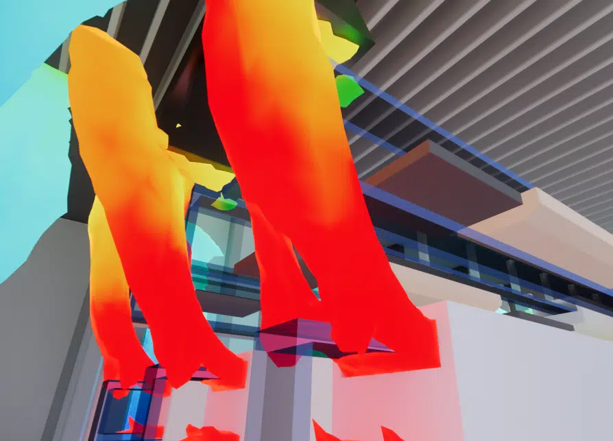
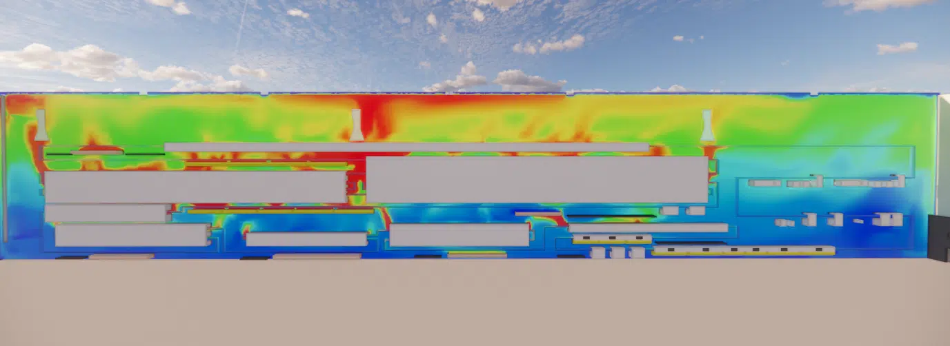
The simulation shows that temperatures are generally acceptable and that the HVAC system is fairly well sized: the air movements generated by the nozzles drive a circulation of about 0.5 m/s throughout the space, including between the production lines, ensuring homogeneous temperatures. Ambient temperatures vary from 36 °C to 42 °C with height (a delta of about 10 °C with the supply air). On the other hand, under the roof, some of the heat-laden air struggles to be extracted and the temperature can reach 50 °C: the nozzles in the northern part lie in line with the extract hoods, creating a by-pass; in the centre, hoods too close to the furnaces have their suction disturbed, and their surfaces are insufficient for the size of the thermal plumes.
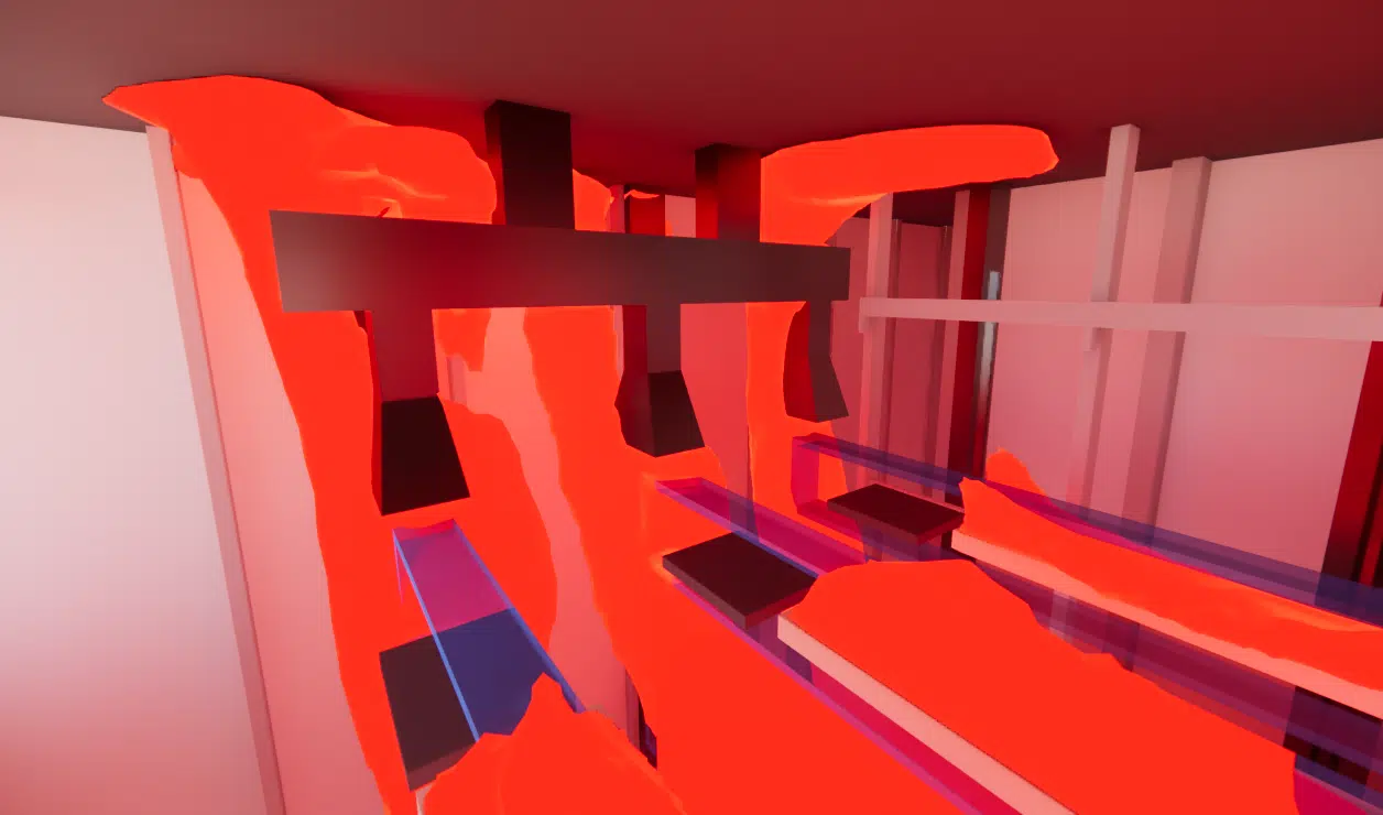
Following this first simulation, EOLIOS recommended moving the supply ducts on the north wall so they blow in more strategic directions and do not disturb the local suction of the hoods, and removing the nozzles over the last 2 metres of the ducts (the cold air blown at that height being directly drawn into the extractions, creating a by-pass that does nothing to cool the lower part).
The teams also reworked the hood suction surfaces — to remove the gaps between two hoods — and, where possible, partitioned off the furnace exits and the hoods (particularly to the north and south). This partitioning does not need to be perfectly airtight: the point is to guide the thermal plumes leaving the furnaces.
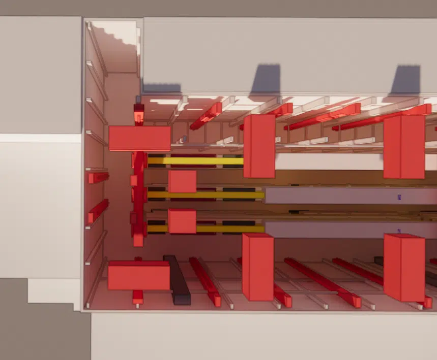
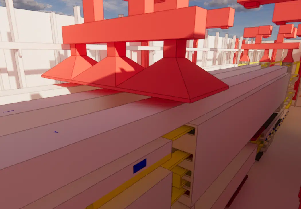
The partitioning prevents the heat released at the ends of the line from dispersing into the environment; moving the ducts towards the north and lowering the nozzle height distribute fresh air better in the important zones; increasing the suction surfaces in the centre captures the plumes of the main furnaces more effectively. The result: ambient temperatures of 35 °C to 40 °C at line level, 41 °C to 45 °C under the roof (peaks of 50 °C in the centre) — about 2 °C lower than with the existing design at every point.
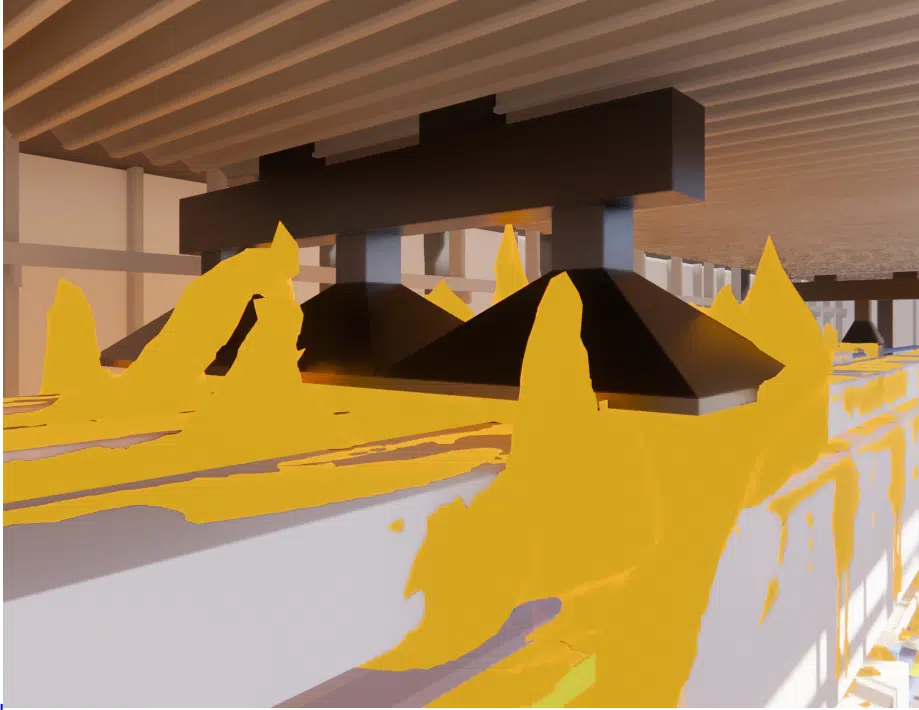
In winter conditions, the outdoor temperature is at its lowest and the internal heat gains are considered at their minimum. Despite the two supply systems being switched off, the air remains in motion at every point — no problematic dead zone. Temperatures vary from 15 °C at floor level to 20 °C at the top floor of the line, and from 20 °C to 25 °C under the roof (peaks of ~30 °C in the central and northern parts, due to the reduced hood-extraction flow rate in winter).
However, very cold temperatures are reached at the louvres: one blows air at a temperature below 0 °C, strongly cooling the room and creating discomfort for the operators nearby. We advised closing this louvre in very cold weather. Otherwise, the winter thermal regulation is well suited: homogeneous temperature and supply air reaching all the important zones.

A pollutant-dispersion study was carried out for the summer situation. It shows that the hoods above the acid tanks at the start of the line capture all of the emissions, whereas part of the emissions from the pre- and post-leaching tanks is less well extracted and risks stagnating under the roof, in the low-velocity zone beneath the fans in the northern part.
A third scenario, involving the closing of a louvre deemed counterproductive, showed that this closure promotes the stratification of the hot air, improving the thermal draught and the extraction of heat-laden air. This confirms the importance of the correct placement of extractions and ventilation openings: the recommendations encourage adding targeted ventilators and closing certain openings to optimise stratification.
Expertise: industrial ventilation, heat capture & air quality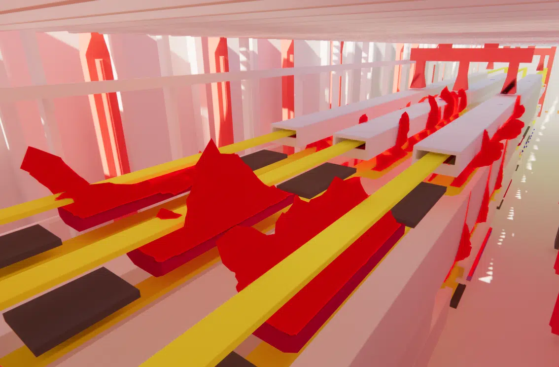
The study covers the thermal-regulation system of a high-temperature-process plant, verified and optimised through CFD simulation. Built around four areas — outdoor-air diffusion, temperature distribution by season, operator comfort and pollutant extraction — it led EOLIOS to propose a new configuration (hoods, supply ducts and nozzles) delivering better heat extraction in summer and a better distribution of fresh air in the important zones.
The simplest thing is to talk it through together. Our engineers will reply with an initial technical read.