Thermo-aeraulic study at Höganäs Belgium: lower the temperatures and improve heat dissipation, particularly in the melting hall.
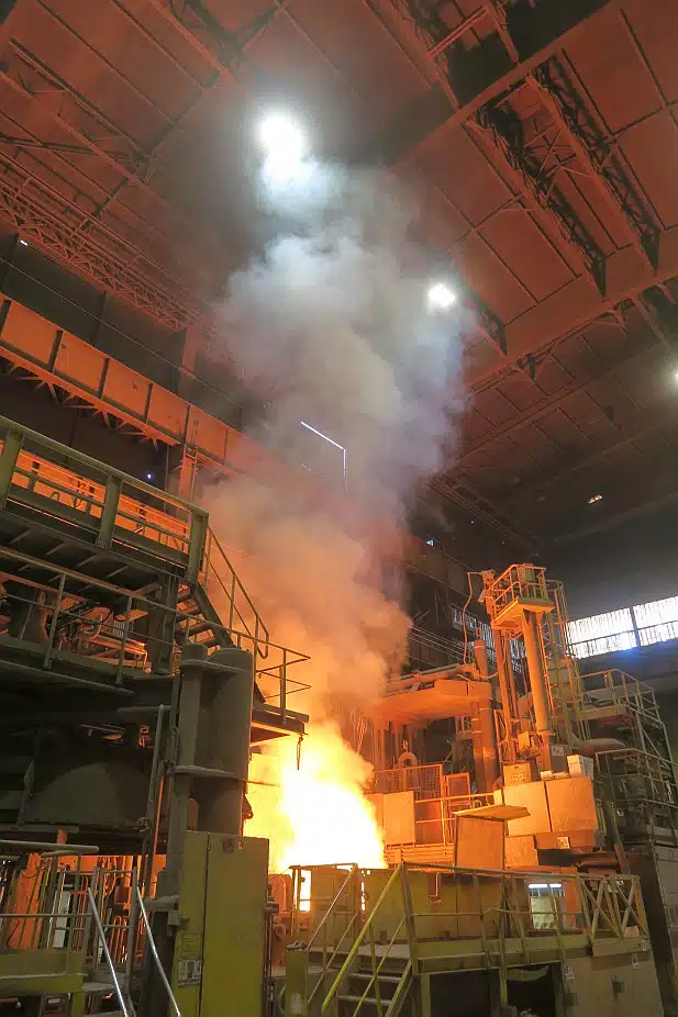
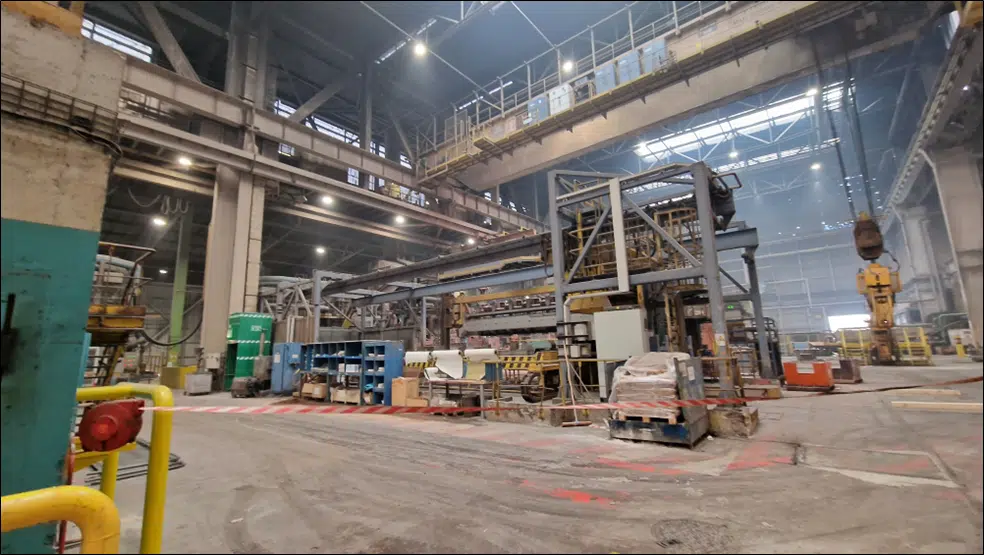
EOLIOS carried out a thermo-aeraulic audit of the Höganäs Belgium site. EOLIOS conducted a thermo-aeraulic audit at the Höganäs Belgium site, a company specialising in the metallurgy of highly alloyed powders. The main objective of this study was to lower the temperatures and improve heat dissipation, with a particular focus on the melting hall, where the two furnaces are located.
This initiative aimed to increase operator comfort throughout the production process. The central challenge of the project was to master the specific thermo-aeraulic phenomena linked to the various manufacturing stages at extremely high temperatures.
The essentials. EOLIOS audited the thermal comfort of the Höganäs Belgium steelworks (Ath), specialising in powder metallurgy. Identification of the air inlets, smoke tests and a thermal camera fed a CFD model of the melting hall (3T and 5T furnaces). Two compared scenarios show that new roof extractors, with the fans shut down, remove the heat far better and lower the working temperature.
This audit examines the ventilation and the openings to identify the first possible improvements.
A thermo-aeraulic audit combines a survey of the openings, smoke tests and thermography to map, on site, the air flows and the heat sources before any modelling. It provides the data of a smoke audit that then feeds the simulation.
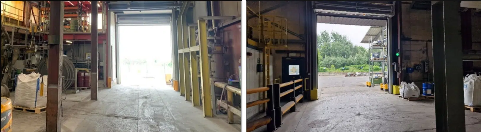
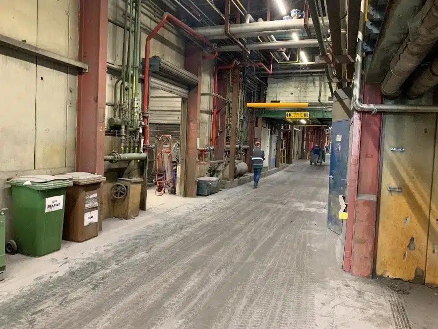
Two large doors at each end of the building generally remain open on the ground floor, letting air in. Another door, leading to the storage hall, is often open, allowing air to leave the study area. All the plant doors act as air inlets, causing significant fresh-air infiltration when open, which can cause discomfort in winter.
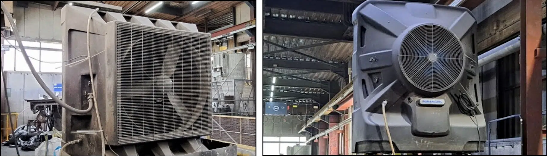
Air inlets are also present on the upper floor of the building, and to improve the comfort of the technicians working near the furnaces, several fans have been installed on the first floor.

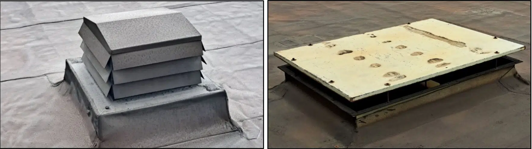
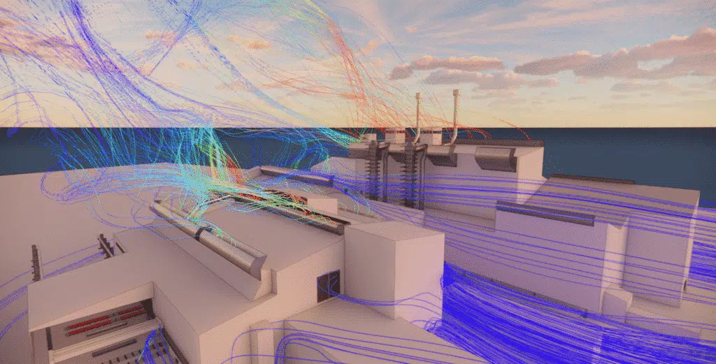
The furnaces generate a large amount of heat that rises towards the roof. To lower the temperature on the building's upper floor, fans are placed on the roof, facilitating the discharge of heat to the outside. The roof is equipped with various natural air-extraction devices.
A smoke test in an industrial building is a method used to assess thermal comfort and air quality inside the building.
To assess thermal comfort, smoke is used to visualise air movement and the air currents inside the building. This makes it possible to detect the areas where there are excessive draughts or air-circulation problems, which can lead to uncomfortable temperature zones.
Regarding air quality, the smoke test makes it possible to demonstrate the air paths inside the building. It highlights unwanted air infiltration, leaks in the building envelope, airtightness defects and ventilation problems. By visualising the movement of the smoke, it is possible to identify the areas where the air is stagnant, where contaminants can accumulate and where ventilation is insufficient.
These tests allow EOLIOS engineers to identify the potential problems related to thermal comfort and air quality, and to take the necessary measures to improve the conditions inside the building. This can include adjustments to the heating, ventilation and air-conditioning system, repairs to improve the building's airtightness, or modifications to the layout of the interior space to optimise air circulation.
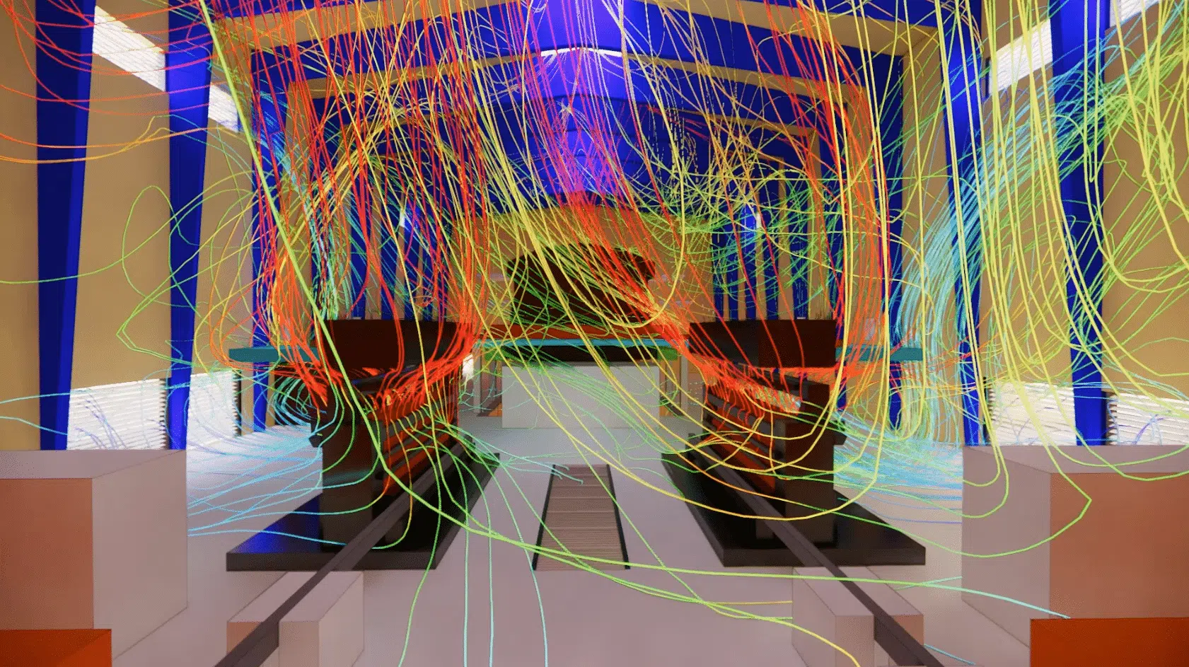
The smoke tests reveal various air-circulation patterns in the building. On the upper floor, the air heads outside through the open windows, while part of it rises towards the roof. Near the fans, the hot air is pushed back down, creating a homogenisation of the temperature, although causing an increase in heat in the lower areas.
The fans near the furnaces generate air movement but do not promote better heat removal. In some areas, a two-way flow occurs, with hot air rising towards the extraction loops and cooler air heading towards the furnaces. Thermal stratification phenomena also occur, separating the hot-air and cold-air zones.
This section aims to highlight the main sources of the thermal phenomena and the areas that are more or less dense in heat. The thermal-camera analyses are used to establish a representation of the hot and cold zones in order to support the numerical studies.
Computational Fluid Dynamics (CFD) is a numerical approach for analysing fluid flows in a given environment, notably in building design. It makes it possible to obtain information on air velocities, pressures and temperatures inside and around built spaces. This method uses partial differential equations to solve the phenomena numerically, taking into account the boundary conditions such as the building's aeraulic effects, the internal heat gains and the air-conditioning systems. CFD simulations are essential for optimising the ventilation and air conditioning of large spaces, guaranteeing optimal comfort.
The partial differential equations require boundary conditions to be solved. These are established on the basis of the on-site measurement data and the information from the project management. For a steady-state study in a space open to the outside, the characteristics of the walls (material, physical properties, viscosity, temperature) must be defined, as well as those of the surfaces exposed to the outside (flow direction, velocity, pressure, temperature, surface coefficients). It is crucial to ensure the stability of the computation when defining these conditions, as the equations are solved iteratively to approach the solution.
The solver of the code used approximately solves the equations at each node of the mesh, respecting the fundamental principles of physics (conservation of mass and energy). It uses the standard k-epsilon turbulence model, which solves for two variables: the turbulent kinetic energy and the rate of dissipation of kinetic energy. This model is widely used in industrial and HVAC applications because of its good convergence speed and its acceptable memory requirements. For thermo-aeraulic studies, the effect of the radiative exchanges between the walls, the thermal conduction, the thermal draught and gravity are taken into account. The studies are carried out on the whole building without establishing a symmetry cut.
The k-epsilon model is a two-equation turbulence model (turbulent kinetic energy and its dissipation rate). Widely used in HVAC and industry, it offers a good compromise between accuracy, convergence speed and memory requirements.
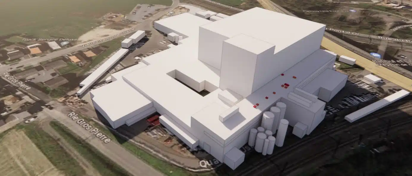
As part of the CFD study, the entire building was modelled in order to take into account the various aeraulic masks created by the different modules of the site.
The furnaces and the internal configuration of the melting building were modelled from the site data, as were the fans and the openings affecting the air movements. The aim is to obtain a precise representation of the complex air movements specific to these premises.
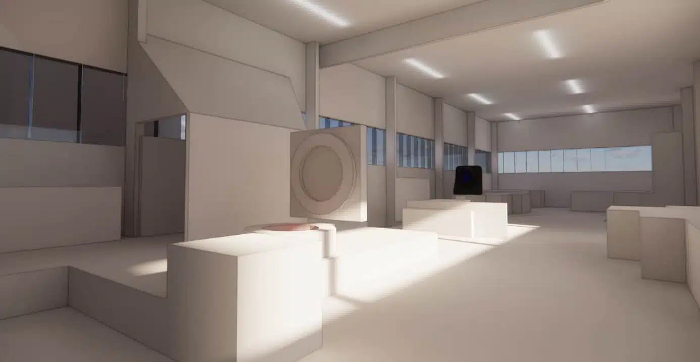
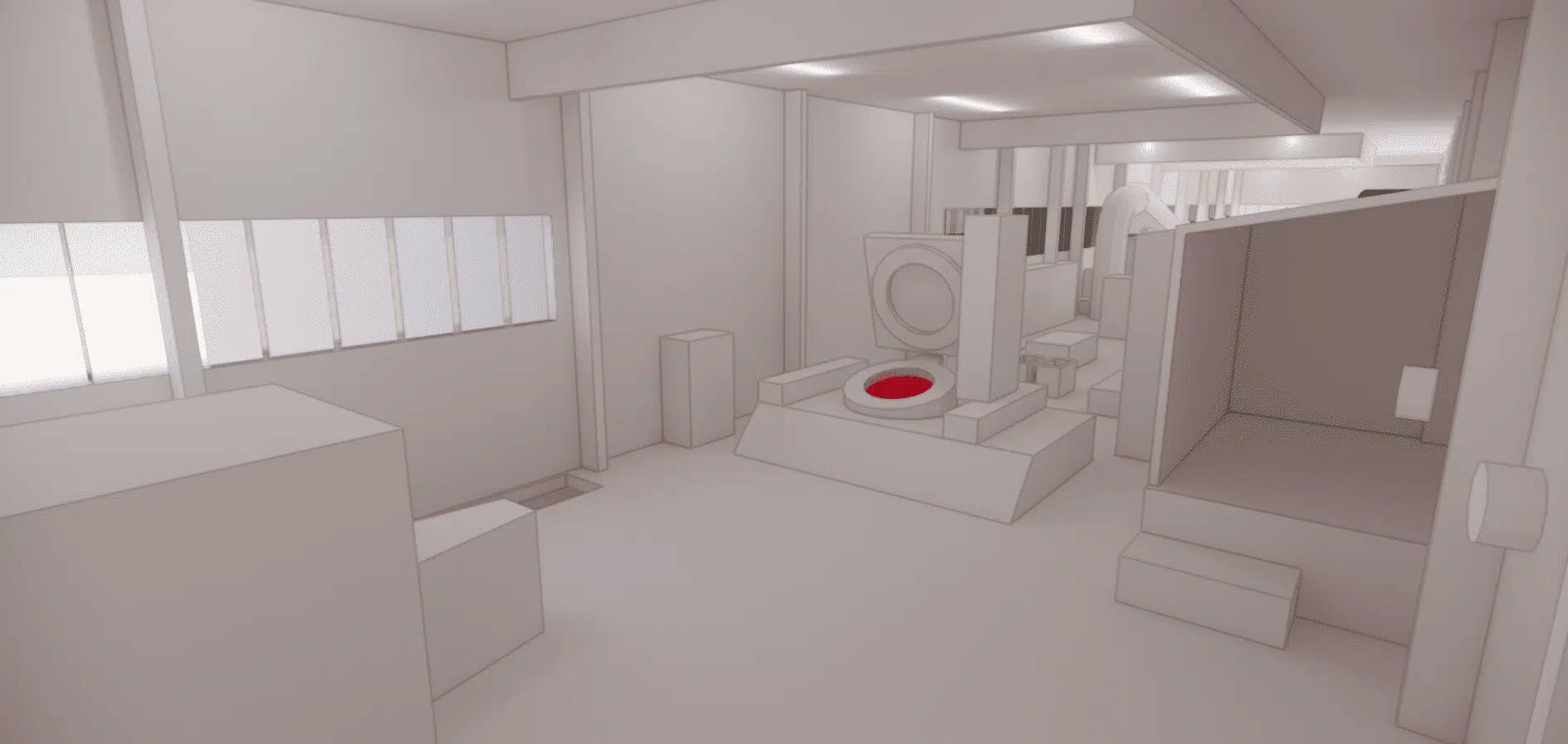
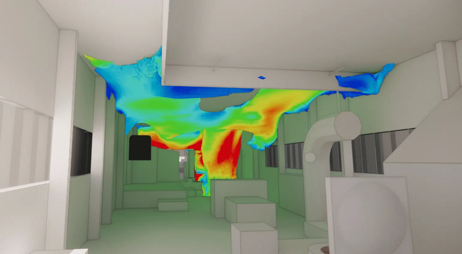
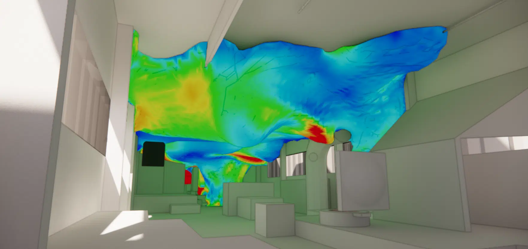
The aim of the studies was to highlight the thermal phenomena present on the site using two distinct scenarios: a baseline scenario with conditions similar to those of the audit and another scenario with conditions allowing an optimisation of the heat extraction.
The audit revealed an absence of thermal rise on the ground floor, unlike the first floor where the furnaces and the preheating of the moulds generate high temperatures. It also highlighted a lack of air extraction under the roof, preventing the effective discharge of heat.
An insulation study was carried out, recommending an adequate insulation thickness. However, the indoor temperature depends more on the air movements and the heat sources than on the insulation.
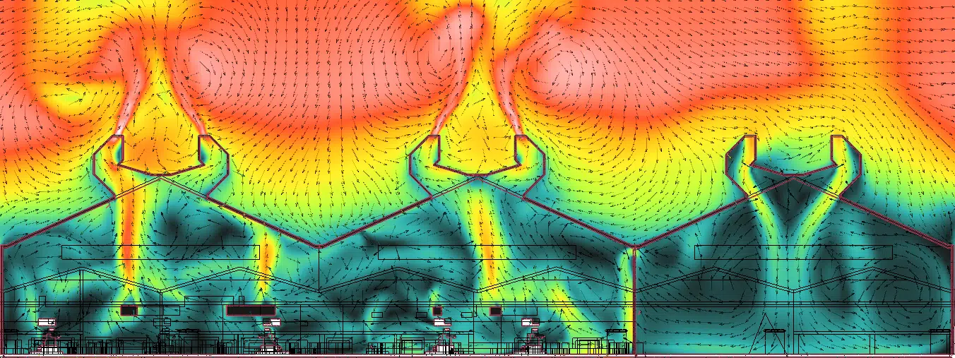
The first scenario showed similarities with the audit, revealing separated air masses due to insufficient roof extraction.
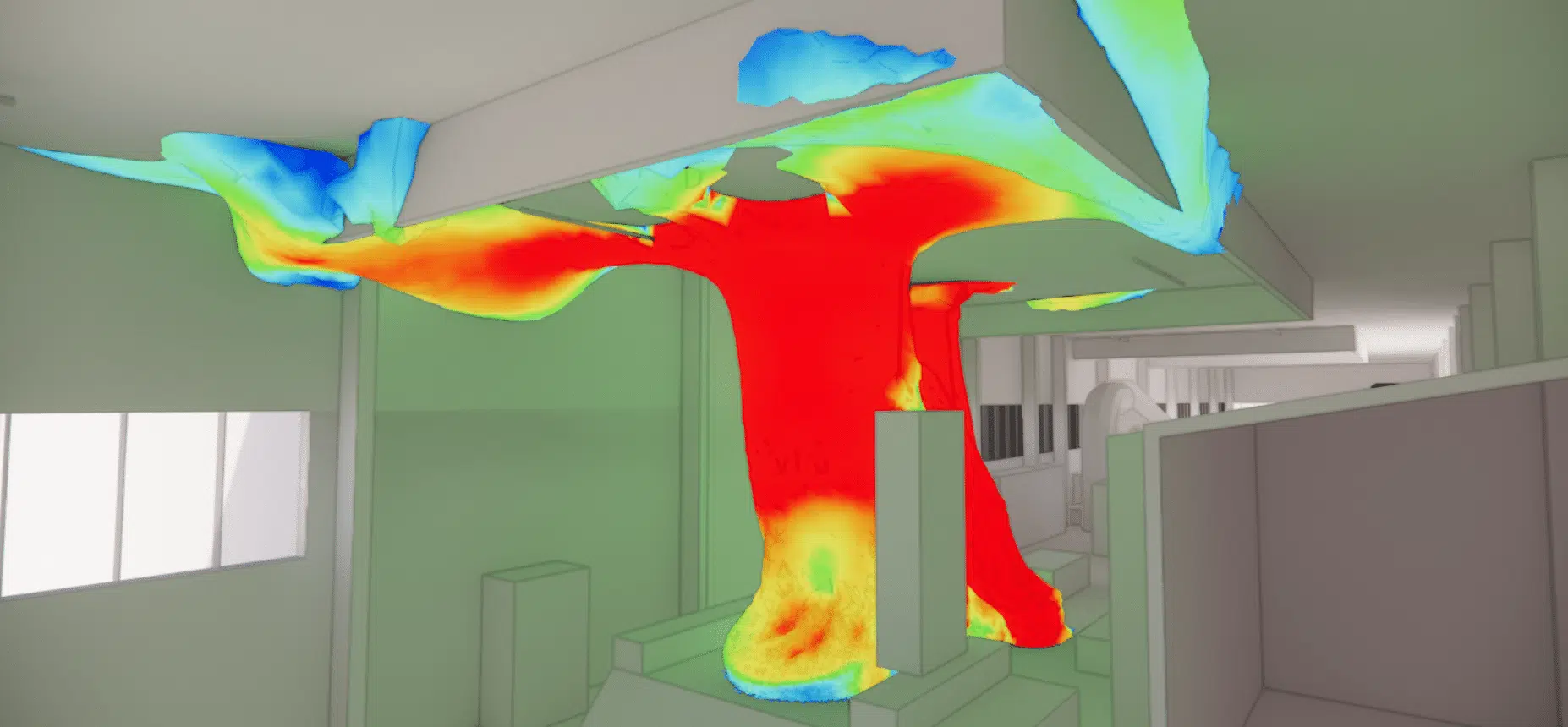
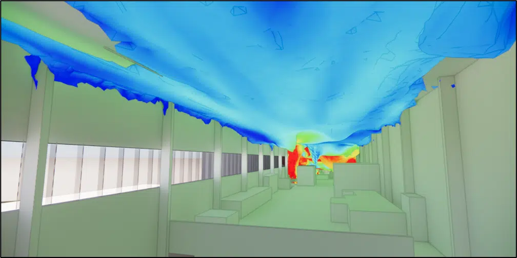
The second scenario implemented new roof-extraction systems and shut down the fans, significantly improving heat extraction, reducing heat diffusion and improving air quality. However, hotter zones persist around the heat sources, suggesting a possible increase in the number of extraction systems.
A temperature isosurface links all the points in space at the same temperature (for example 40 °C). It visualises at a glance the volume occupied by the hot air and its retreat between the baseline scenario and the optimised scenario.
Key takeaway. In a melting hall, insulation matters less than mastering the air movements: it is the extraction of the hot air at the roof, more than the insulation thickness, that lowers the temperature felt by the operators.
Thermal comfort, smoke tests and heat extraction in a melting hall.
By discharging the hot air as high as possible. The study shows that new roof extractors, with the fans shut down, remove the heat far better than air mixing. A similar approach was carried out on our project natural ventilation of a steelworks.
It makes the real air trajectories visible using a non-polluting tracer smoke. It reveals infiltration through the doors, stagnation zones and thermal stratification, impossible to perceive with the naked eye.
The fans placed near the furnaces mix the air without removing it: they push the hot air down and warm the lower areas. By shutting them down and opening roof extractions, the heat leaves the building by thermal draught.
No. The insulation study recommends an adequate thickness, but the indoor temperature depends mainly on the air movements and the heat sources. Without effective extraction, insulation alone is not enough.
The thermal camera maps the real hot and cold zones on site; these readings serve as input and calibration data for the CFD model, which then extends the analysis to the whole volume and to scenarios that were not carried out.
Explore our expertise, projects and technical papers to go further than the FAQ.
CFD thermo-aeraulic study of a steelworks (Höganäs Belgium, Ath) for the optimisation of operator comfort: on-site audit (identification of air inlets, smoke tests, thermal camera), complete 3D model of the melting hall (3T and 5T furnaces) and CFD simulations comparing a baseline scenario with an optimised roof-extraction scenario to remove the heat and improve air quality.
The easiest way is to talk it through together. Our engineers will reply with an initial technical read.