Thermo-aeraulic study of a steelmaking site: optimise the ventilation, improve thermal comfort and strengthen the air quality of the production areas.
In an industrial environment subject to strong emissions of heat and pollutants, natural ventilation shows its limits. Through an analysis combining on-site measurements and CFD simulation, EOLIOS studied the real behaviour of the airflows and proposed concrete solutions to optimise ventilation, improve thermal comfort and strengthen air quality in the production areas.
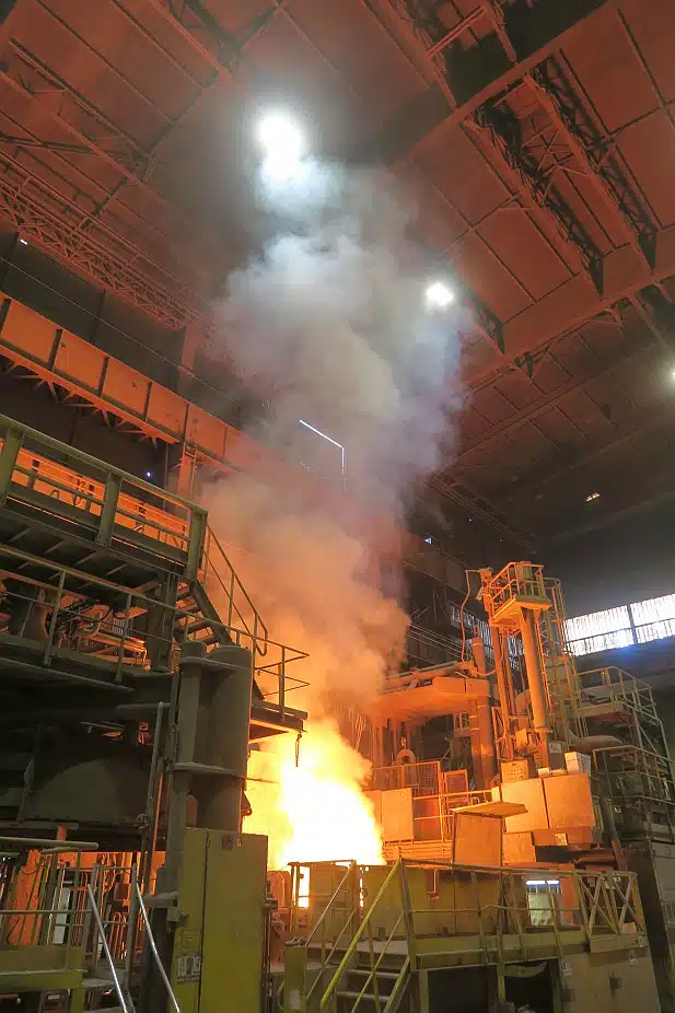
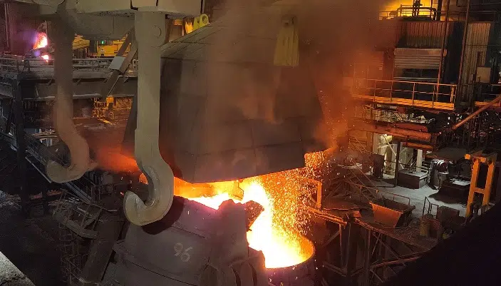
At the heart of a site operating around the clock, subject to extreme temperatures and massive emissions of metallurgical fumes, the heat generated by the converters, the ladles of molten metal and the continuous casting demands rigorous management of the airflows.
With temperatures approaching 1,600 °C and tens of thousands of m³/h in motion, ventilation relies on a complex balance between fume extraction and fresh-air supply.
The essentials. On a steelmaking site in production around the clock, molten steel (about 1,600 °C) releases heat, metallic fumes, CO and fine dusts. An on-site audit (anemometry, smoke tests, infrared imaging) and a calibrated 3D CFD model, solved in steady and transient states, revealed stratification under the roof and insufficient extraction. Reopening louvres facing the wind, roof aerators and a better distribution of the openings raise the extracted flow rates and lower temperatures and pollutant residence times, without heavy works.
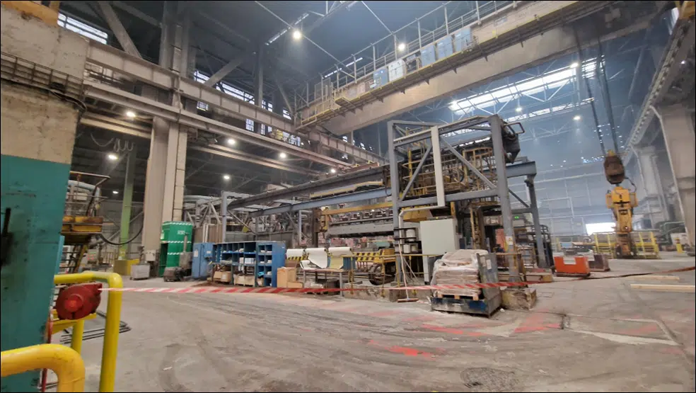
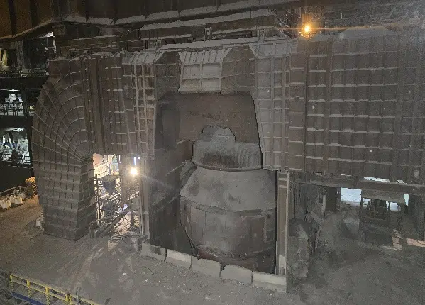
At the heart of a steelmaking site operating around the clock, subject to extreme temperatures and massive emissions of metallurgical fumes. In this gigantic industrial hall, the heat generated by the converters, the ladles of molten metal and the continuous casting demands rigorous management of the airflows.
The processes that transform pig iron into steel generate significant emissions of atmospheric pollutants: carbon monoxide (CO), fine metallic dusts, compounds of manganese, chromium, zinc or crystalline silica. These fumes, often invisible to the naked eye, can concentrate locally in the absence of effective extraction. Beyond the risks of chronic exposure for the operators, these pollutants are governed by strict Occupational Exposure Limits (OEL). Ventilation plays a crucial role in quickly removing the harmful gases and diluting the suspended particles, in order to preserve a working environment compliant with health and regulatory requirements.
With temperatures approaching 1,600 °C and air volumes in motion of several tens of thousands of cubic metres per hour, the site's ventilation relies on a complex balance between fume extraction and fresh-air supply. Any disturbance can affect air quality, operator safety and the energy efficiency of the installations.
Thermal draught is the upward movement of hot air, which is lighter and escapes through the high openings, drawing fresh air in below. In a steelworks, the sources at 1,600 °C make it a very powerful natural-ventilation driver.
Steel production relies on a sequence of highly energy-intensive processes, generating large volumes of heat, gas and particles. The general principle rests on the following stages:
Each stage contributes to a localised production of heat and pollutants, often concentrated around the converters, the ladle-transfer zones, the continuous casting or the deslagging equipment. Working temperatures can exceed 1,600 °C, generating rising hot-air flows, gas emissions (CO, CO₂), fine particles and metallic dusts. These phenomena have a direct impact on the thermal stratification, the behaviour of the airflows and the dispersion of pollutants. Characterising these emissions is part of our expertise in the measurement and impact study of air pollution.
Understanding these mechanisms is essential to size a ventilation system able to renew the air efficiently, remove the excess heat and limit operator exposure.
The steelmaking process generates a wide variety of atmospheric pollutants, directly linked to the high temperatures and the chemical reactions carried out in the converters and during the metallurgical treatments. The main compounds emitted are:
These substances, sometimes invisible to the naked eye, can accumulate in the high volumes or disperse slowly if no effective extraction mechanism is in place.
Regulations impose Occupational Exposure Limits (OEL) to frame exposure to hazardous substances. These thresholds, expressed in mg/m³ or ppm, aim to limit short- and long-term health effects (respiratory disorders, poisoning, chronic diseases).
The compounds present in the fumes, such as CO or metallic particles, are strictly regulated. Exceeding these thresholds requires immediate corrective measures: capture at source, localised ventilation, or the wearing of suitable personal protective equipment (PPE).
Occupational Exposure Limits set the maximum concentrations of pollutants tolerated in the air breathed by operators, over 8 hours or over short periods. They serve as a criterion for sizing the extraction and the capture at source.
Chronic exposure to excessively high pollutant concentrations can lead to respiratory pathologies, neurological disorders or systemic effects. Among the risks recognised in the steel industry:
Controlling indoor air quality is therefore a matter of public health and of responsibility for the operator.
During the audit, spot measurements characterised the pollutants, in particular the fine particles. Some zones, such as those under the roof or near the equipment, nevertheless remain inaccessible. To complement them, EOLIOS implemented a scalar CFD modelling, virtually reproducing:
This approach makes it possible to identify the at-risk sectors requiring targeted corrective actions.
All the data collected, enriched by the CFD simulation, forms a solid basis to support the regulatory procedures, in particular:
Unlike other industrial environments equipped with controlled mechanical ventilation, this site relies mainly on natural ventilation. It rests on two physical principles: the temperature difference between inside and outside (creating a vertical thermal draught) and the wind pressure on the façades.
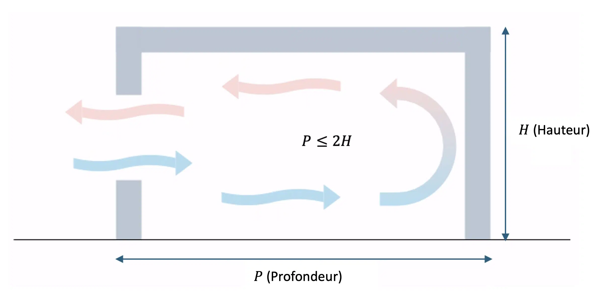
The hot air, lighter, rises and escapes through the roof aerators, while the fresh air enters through the low openings. This passive approach, without any motorised system, takes advantage of the natural conditions to ensure air renewal. Robust and economical, this mode of operation nevertheless raises several major issues in an intensive industrial context:
If natural ventilation ensures part of the general air renewal, it cannot on its own guarantee the rapid and localised removal of the pollutants generated at the production stations. The site therefore relies on a targeted mechanical ventilation system, designed to draw off the critical emissions at their point of origin.
This principle relies on extractor hoods, sensors and capture devices positioned as close as possible to the sources (converters, furnaces, full ladles, continuous casting, deslagging zones). They capture fumes, gases and particles before their dispersion, limiting their spread in the hall and keeping the concentrations below the OEL thresholds.
This type of installation involves several technical constraints: a precise sizing of the extraction flow rates according to the intensity of the emissions, an effectiveness strongly dependent on the equipment configuration and the proximity of the sensors, and a non-negligible energy consumption. Hence the interest in intelligently combining it with natural ventilation to design a balanced hybrid system, both high-performing and economical.
To meet these challenges, EOLIOS carried out a complete thermo-aeraulic study, combining on-site measurements and numerical CFD simulations. This analysis made it possible to:
Before considering any optimisation, it is essential to understand precisely how the air circulates within the site. EOLIOS deployed a rigorous aeraulic-audit methodology, combining on-site measurements and numerical modelling. Over several days, the engineers analysed the behaviour of the air masses and the interactions between natural ventilation and the industrial emissions, to obtain a complete view of the air movements and identify the areas for improvement.
Using a calibrated anemometer, the air velocities were measured at the building's inlets and outlets, as well as within the production halls, in order to quantify the airflows and assess the intensity of the natural air renewal.
In parallel, temperature readings were taken at different heights. They revealed a marked thermal stratification: hot air accumulates at height while cooler air stays at ground level. These vertical gradients reflect a slow movement of the hot-air masses, sometimes trapped under the roof in the absence of an effective draught.
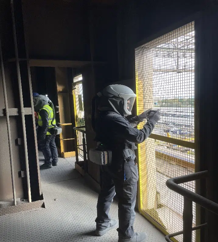
This detailed analysis made it possible to identify the zones of thermal discomfort and the poorly ventilated sectors, where natural extraction is insufficient.
The smoke tests make it possible to visualise in real time the direction and speed of the airflows. EOLIOS used a cold-smoke machine, suited to industrial environments: by diffusing a fine, light smoke in different zones, it was possible to trace the path of the air, spot the stagnation or recirculation zones and identify the dominant currents. The results revealed several notable phenomena:
These visual observations formed a valuable basis for the CFD modelling, making it possible to validate the assumptions and adjust the simulation parameters.
For a global view of the thermal balance, EOLIOS used infrared imaging. Using a high-resolution thermal camera, the engineers analysed the surfaces of the equipment and infrastructure in direct interaction with the air, which made it possible to identify:
These readings were essential to define the boundary conditions of the CFD model: the surface temperatures were used to calibrate the thermal fluxes, ensuring a simulation faithful to the real behaviour of the site. The results confirmed the need for an optimised ventilation, able to remove the excess heat while ensuring sufficient air renewal.
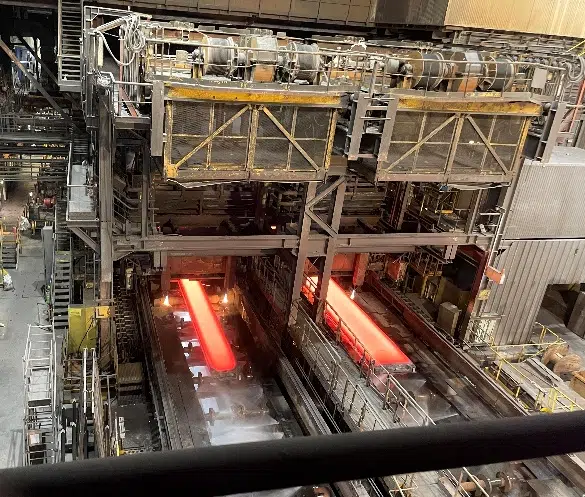
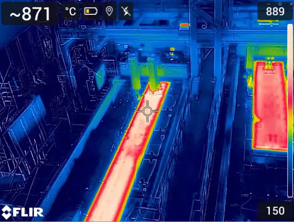
The audit made it possible to list and characterise all the site's openings: service doors, side louvres, static roof aerators, dust-extraction hoods. Each opening was geo-referenced and measured to quantify its contribution to the overall air renewal.
The air-velocity measurements at inlet and outlet revealed significant disparities: some inlets are heavily used, others remain little active for lack of a favourable position or a pressure differential. In particular, the doors exposed to the prevailing wind show high air velocities, generating locally uncomfortable draughts. These observations underline the need for a more homogeneous distribution of the openings and a finer regulation.
The measurements and smoke tests made it possible to draw up a detailed mapping of the aeraulic flows in the halls, highlighting several stagnation zones where the air is renewed more slowly and where the fumes tend to accumulate. A particular area of vigilance concerns the space under the roof, where heat and fumes concentrate without being effectively removed, a phenomenon accentuated by the thermal stratification.
The study confirmed the major impact of the manufacturing processes on the aeraulic dynamics. The molten-metal transfers, the deslagging sequences and the continuous-casting operations generate strong emissions of heat and fumes, profoundly modifying the airflows. These phenomena must be integrated from the design of the natural-ventilation devices, to favour the removal of the fumes and reduce operator exposure.
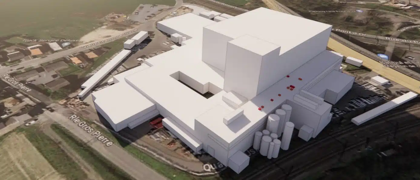
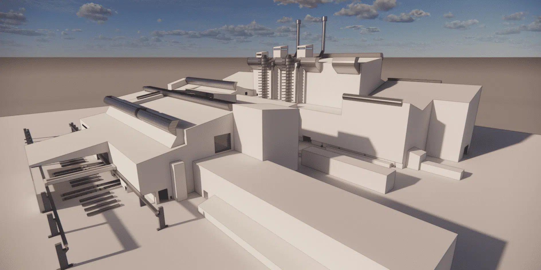
To turn the audit observations into concrete recommendations, EOLIOS relies on CFD simulation (Computational Fluid Dynamics), which numerically reproduces the behaviour of the air and the heat with unrivalled precision. The first step is to model the whole site in 3D: from the field measurements, the client's drawings and satellite imagery, the engineers reconstructed a complete geometric model, integrating the production halls and their immediate surroundings.
All the structures influencing the airflows (walls, openings, frameworks, equipment, aerators) were faithfully integrated, while the secondary elements were simplified to optimise the computing power. The internal heat sources were carefully modelled: each equipment item with a high thermal input (converters, ladles, slabs, dryers) was parameterised from the surface temperatures measured on site.
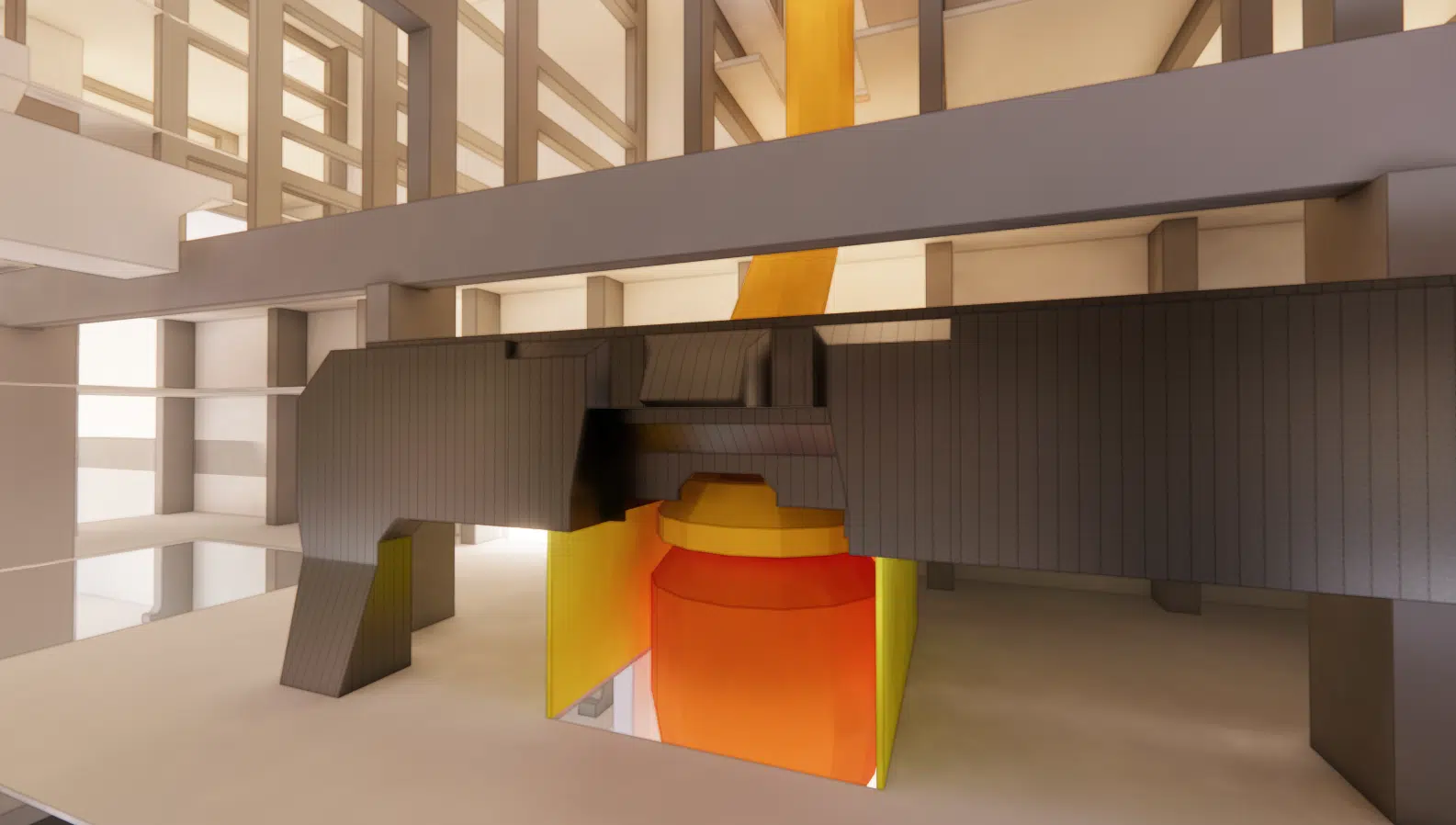
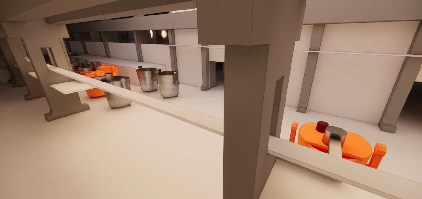
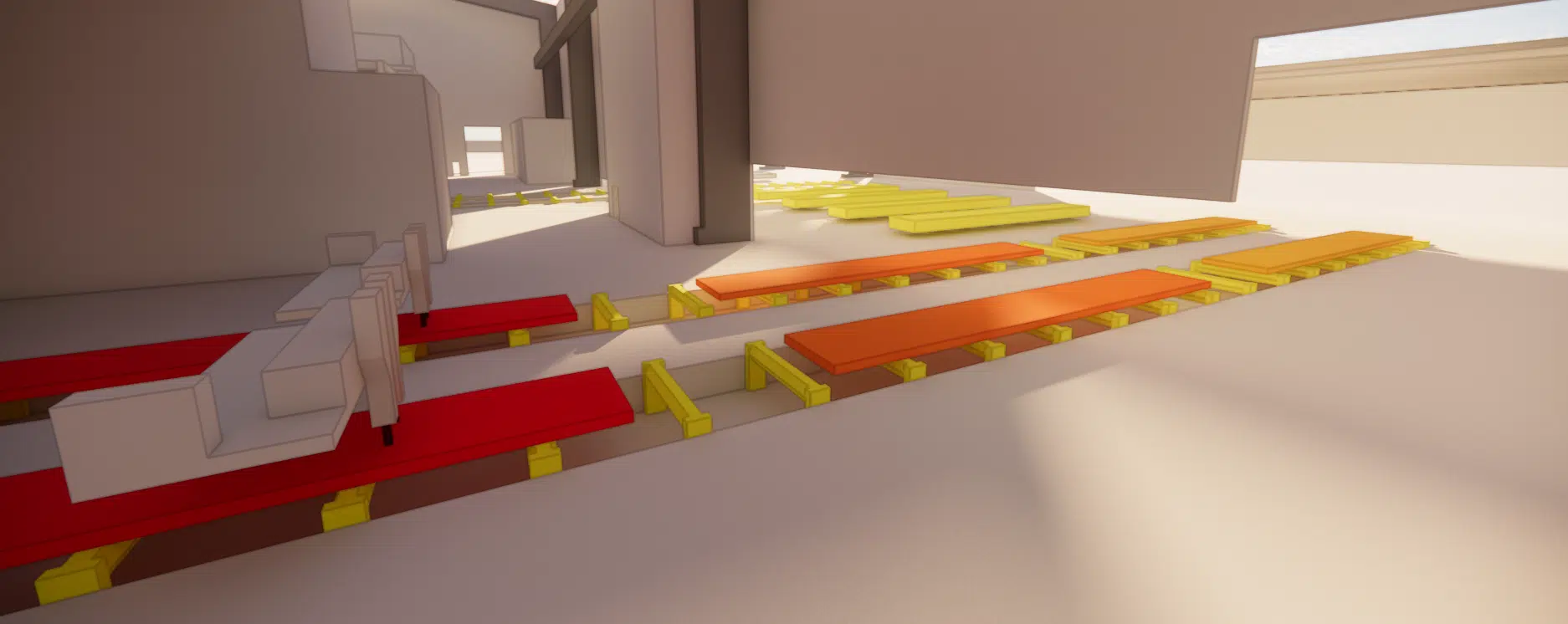
Finally, the existing ventilation devices (louvres, aerators, hoods) were integrated as boundary conditions, with flow rates or velocities from the audit. This model makes it possible to assess the current performance of the system, but also to test different configurations virtually to guide the design choices.
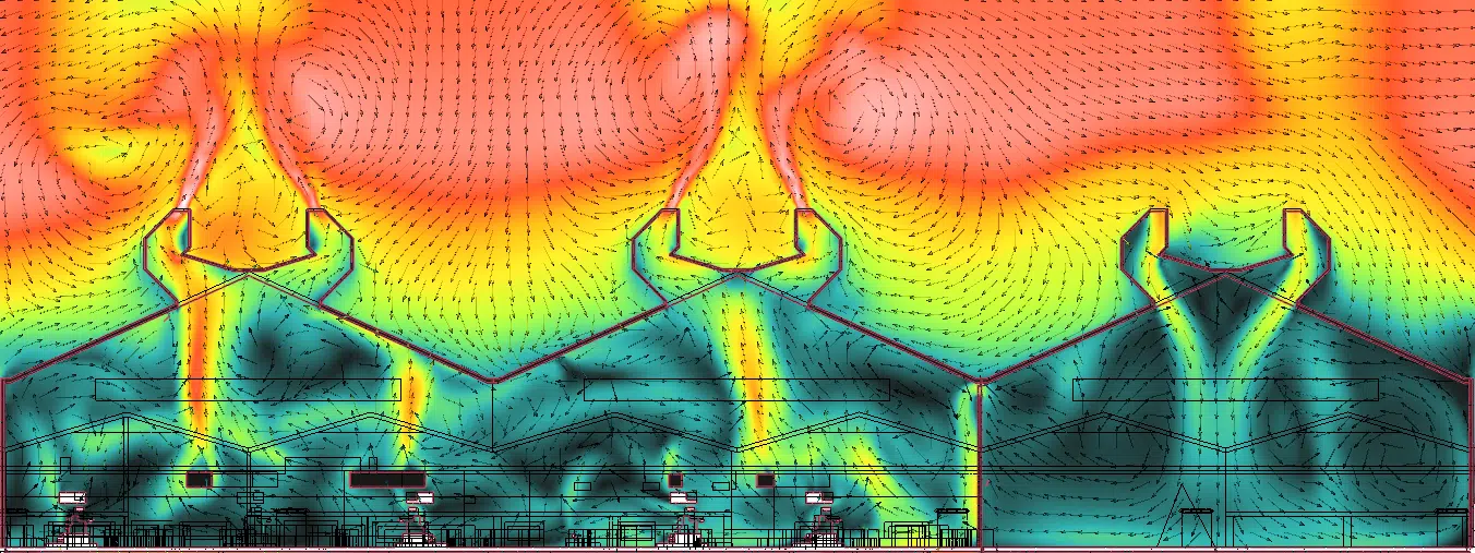
EOLIOS uses a numerical approach based on the finite-element method, which solves the equations governing the air movements and the thermal exchanges in the simulated volume. A very fine 3D hybrid mesh was generated, with specific refinement around the intense-heat zones and the openings. A first series of calculations was carried out in steady state, on the nominal conditions observed during the audit, to validate the performance of the existing system and identify the critical zones. The simulations highlighted:
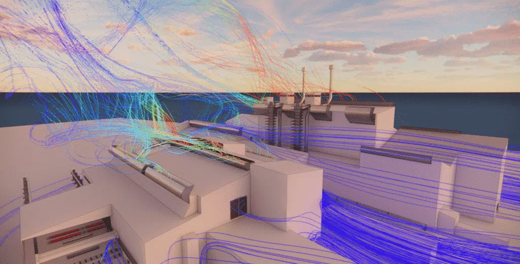
One of the great advantages of the simulation is that it gives access to data inaccessible by direct measurement: flow rates through the roof aerators, which cannot be safely instrumented, and air velocities above equipment hotter than 1,200 °C. In addition to the steady-state calculations, some critical zones were the subject of a dynamic analysis in transient state, to better understand the evolution of the flows and the dispersion of the pollutants over time. Using scalar tracers or emissivity lines, these visualisations make it possible to anticipate the exposure peaks, the fume residence times or the zones of prolonged recirculation.
A steady-state calculation freezes the flow in an average equilibrium; a transient calculation follows its evolution over time. The first validates the overall flow rates, the second reveals the exposure peaks and the residence times of the fumes.
A major asset of CFD is that it allows a rapid exploration of improvement scenarios, virtually testing different modifications without disrupting operations. EOLIOS simulated several configurations by varying the opening or closing of existing louvres, the addition of extra aerators and the change of their positioning or orientation. To ensure the robustness of the solutions, the simulations integrated several extreme scenarios:
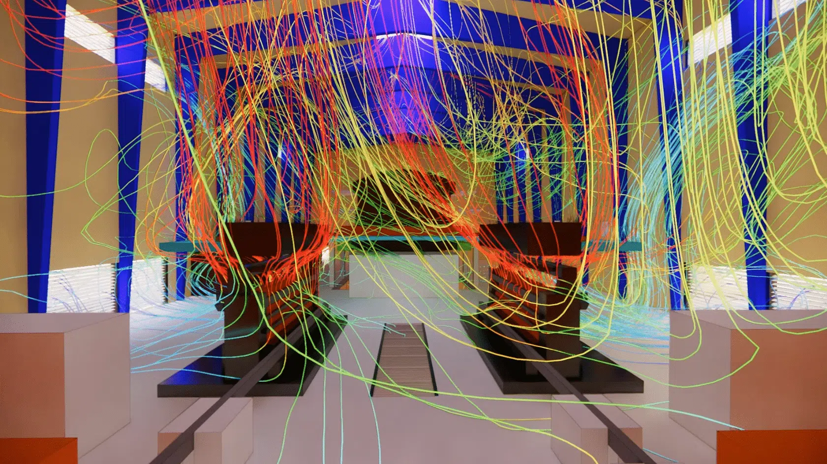
These simulations made it possible to identify the most effective configurations. Among the effective solutions: the reopening of louvres on the façades exposed to the prevailing wind, the targeted addition of static roof aerators in the stagnation zones, and a better distribution of the openings between the halls. The benefits could be quantified: increased extracted flow rates, reduced ambient temperatures, improved thermal comfort and shorter pollutant residence time. The results, usable as temperature maps, air-velocity maps, streamlines or comparative balances, make it possible to technically justify the design choices.
CFD makes it possible not only to understand the current operation of the installation, but also to project its evolution and its improvement potential. It is a valuable decision-support tool for operators, engineering firms and safety managers. By precisely identifying the critical zones, the aeraulic malfunctions and the optimisation opportunities, it makes it possible to:
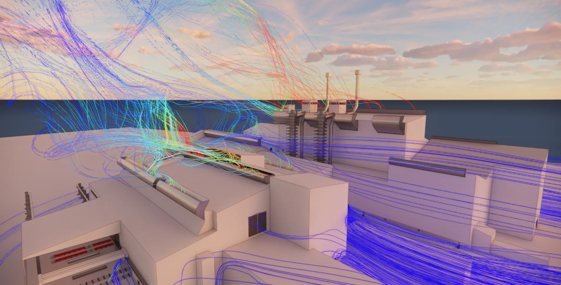
Thanks to the calculations carried out, EOLIOS drew up a detailed mapping of the airflows, the streamlines, the stagnation zones and the flow rates through the whole studied volume. The high-thermal-draught zones, near the converters, the full ladles or the hot slabs, translate into rapid rises of hot air partially channelled towards the aerators. Several critical zones were nevertheless identified:
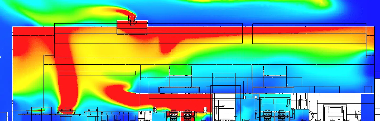
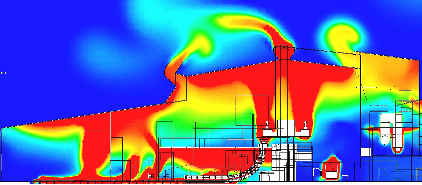
To ensure the robustness of the solutions, the simulations were extended by the study of several unfavourable scenarios, beyond the nominal conditions:
Although occasional, these situations make it possible to test the resilience of the ventilation system and to size the openings to guarantee a minimum air renewal in all circumstances.
From these analyses, EOLIOS tested and compared several optimisation scenarios, virtually adjusting the ventilation devices: reopening inactive louvres on the façades facing the prevailing wind, adding static aerators in the stagnation zones, a more homogeneous distribution of the openings between halls, and recalibrating some mechanical extractions or capture-at-source systems.
One of the most effective scenarios consisted in increasing the air-inlet area on the windward façades and installing new roof aerators. This configuration allowed a significant increase in the extracted air flow rates, a notable drop in the ambient temperatures and a marked reduction in the pollutant residence time, without heavy investment or major interruption of production.
Key takeaway. In a steelworks, the most effective ventilation is not the most expensive: acting on the position and opening of the existing aerators is often enough to restore the thermal draught and lower temperatures and pollutants, without heavy works or production stoppage.
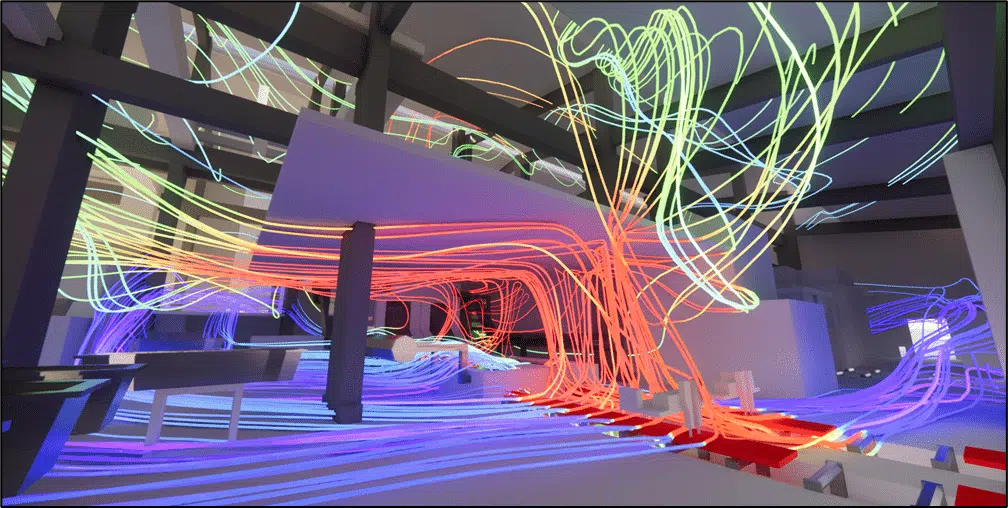
The study made it possible to characterise the indoor air quality and to anticipate operator exposure to the pollutants of the steelmaking process (carbon monoxide, fine and ultrafine metallic dusts, deslagging and slab-oxidation fumes). The simulation integrated scalar CFD studies reproducing the dispersion of the pollutants under several ventilation scenarios. The results highlighted:
Cross-referenced with the audit results and the regulatory references, these analyses made it possible to determine the needs for personal protective equipment (PPE), the requirements for capture at source and the targeted ventilation reinforcements. They also constitute valuable support for an ICPE compliance file, if required.
By combining the field data, the numerical simulations and the safety requirements, EOLIOS proposed a global ventilation strategy adapted to the site's specifics:
This strategy can be implemented gradually, through simple and pragmatic actions, to build a robust, durable ventilation system compatible with the future changes of the site.
Expertise: designing industrial natural ventilationNatural ventilation, OEL and CFD simulation in a steelworks.
It ensures the general air renewal by thermal draught, but is not enough on its own near the sources: it is supplemented by mechanical capture as close as possible to the converters and the casting. A similar approach was carried out on our project natural ventilation of a steelworks.
Occupational Exposure Limits set the maximum admissible concentrations of pollutants (CO, metallic dusts) in the breathed air. Exceeding them requires corrective measures: capture at source, localised ventilation or PPE.
Natural ventilation is robust and economical but hard to control; mechanical capture targets the emissions at source but consumes energy. Combining them gives a hybrid system that is both high-performing and frugal.
It gives access to data inaccessible by measurement: flow rates through the roof aerators, air velocities above equipment hotter than 1,200 °C. It also allows scenarios to be tested (summer without wind, winter with adverse wind) without disrupting production.
Reopening louvres on the façades facing the prevailing wind, targeted addition of static aerators in the stagnation zones and better distribution of the openings between halls. Result: higher extracted flow rates, lower temperatures and shorter pollutant residence times, without heavy works.
Explore our expertise, projects and technical papers to go further than the FAQ.
CFD thermo-aeraulic study of a steelworks: on-site audit (anemometry, smoke tests, infrared imaging), complete 3D model calibrated on the heat sources, steady and transient simulations of the flows and pollutants, and aerator-optimisation scenarios for better thermal comfort and air quality compliant with the OELs.
The easiest way is to talk it through together. Our engineers will reply with an initial technical read.